Table of Contents
Advertisement
Advertisement
Table of Contents

Related Manuals for Mine Site Technologies NS40 I.S.


Summary of Contents for Mine Site Technologies NS40 I.S.
- Page 1 NS40 I.S. Wireless Network Switch User Guide NS40_UG_EN_C...
-
Page 3: Table Of Contents
Contents Revision History............................7 Contact Information............................9 About This Manual............................11 Chapter 1: I.S. Wireless Network Switch..........13 1.1 Hardware Overview........................14 1.2 System Layout Overview......................15 1.3 Connectivity..........................16 1.3.1 Composite Fibre Ports....................17 1.3.2 Wireless Access Points....................18 Chapter 2: Installing I.S. Wireless Network Switches......19 2.1 Pre-Installation Planning......................20 2.2 Mounting an I.S. - Page 4 4.4.3 Viewing Wireless Networks..................39 4.4.4 Viewing MAC Address Table..................40 4.4.5 Viewing Ports and STP Status..................41 4.4.6 Viewing AeroScout Status..................42 4.4.7 Viewing Routes......................42 4.4.8 Viewing System Logs....................43 4.4.9 Viewing Kernel Logs....................43 4.5 System tab..........................44 4.5.1 Changing System Settings..................44 4.5.2 Changing the System Administrator Password............44 4.5.3 Managing System Processes..................45 4.5.4 Configuring Network Time..................46 4.5.5 Configuring Location Based Services................46...
- Page 5 Appendix D: Connecting a PC to an I.S. Wireless Network Switch..81 Appendix E: Device Discovery..............85 Appendix F: I.S. Wireless Network Switch Reset and Reboot....87 Appendix G: I.S. Wireless Network Switch Specifications....91 Appendix H: Maintenance Checklist............93 Appendix I: NS40 Regulatory..............95 Appendix J: Warranty and License Agreement........97 J.1 Hardware Warranty........................97 J.2 Software End User License Agreement..................97 Revision C...
- Page 6 NS40 I.S. Wireless Network Switch Revision C...
-
Page 7: Revision History
2012 Mine Site Technologies Pty Ltd. All rights reserved. Mine Site Technologies Pty Ltd reserves the right to make changes to specifications and information in this manual without prior notice. Mine Site Technologies Pty Ltd accepts no responsibility for any errors or omissions contained in this manual. -
Page 9: Contact Information
Contact Information AUSTRALIA - Sydney 113 Wicks Road North Ryde NSW 2113 AUSTRALIA Tel: +61 2 9491 6500 CANADA - Sudbury 1085 Kelly Lake Road Sudbury Ontario P3E 5P5 CANADA Tel: +1 705-675 7468 CHINA - Hangzhou 4F, Building 1 1413 Moganshan Road Hangzhou CHINA 310011 Tel: +86 571 85803320x206... -
Page 11: About This Manual
About This Manual This manual describes features and functions of the NS40 Intrinsically Safe Wireless Network Switch. It provides information about hardware installation, operation, configuration and how to troubleshoot any issues. You will find it easier to use the manual if you are familiar with networking systems and have an understanding of electronics in a network environment. -
Page 13: Chapter 1: I.s. Wireless Network Switch
Chapter I.S. Wireless Network Switch Topics: The Mine Site Technologies Intrinsically Safe Wireless Network Switch (NS40) consists of a managed fibre optic Ethernet switch and • Hardware Overview two 802.11b/g wireless access points. It provides wired and wireless • System Layout Overview network access in hazardous coal mining environments. -
Page 14: Hardware Overview
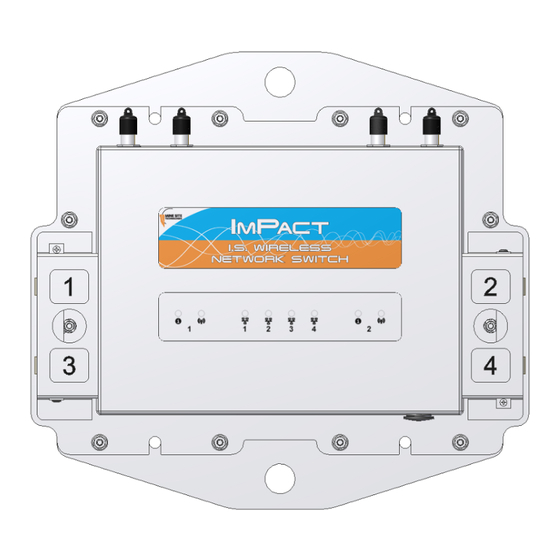
I.S. Wireless Network Switch 1.1 Hardware Overview The features and functions of the NS40 are illustrated below: Description Function Composite fibre port. Power and / or fibre optic connectivity via composite cable, fibre optic cable or DC power cable. Composite fibre port number. By default, composite fibre port 1 is the upstream port. -
Page 15: System Layout Overview
I.S. Wireless Network Switch Description Function LED status Indication Flashing Transmitting or receiving data. Composite fibre port link / The fibre port LEDs indicate the following: Activity LEDs. LED status Indication Fibre transceiver is disabled or has not established a link to the next device. Fibre transceiver is enabled and has established a link to the next device. -
Page 16: Connectivity
I.S. Wireless Network Switch Figure 1: An example of an Intrinsically Safe network The Intrinsically Safe design of the network requires each cell to be individually powered and that electrical power must not travel between them. Fibre optic cables is used to connect between cells to provide network connectivity. -
Page 17: Composite Fibre Ports
I.S. Wireless Network Switch 1.3.1 Composite Fibre Ports Each side of an NS40 unit has two composite fibre port connectors with a crush protection cover. Each connector consists of two electrical contacts and a duplex LC single mode optic fibre (SMOF) receptacle. Note: A protective cover or a mating cable connector must be attached to each port to maintain the IP65 (Ingress Protection) rating of the unit. -
Page 18: Wireless Access Points
I.S. Wireless Network Switch Due to the difference in the fibre orientation, MST composite cable and fibre optic cable can only be connected between ports on NS40 devices marked with a tick in the matrix below. Port 1 Port 2 Port 3 Port 4 Port 1... -
Page 19: Chapter 2: Installing I.s. Wireless Network Switches
Chapter Installing I.S. Wireless Network Switches Topics: This chapter describes mounting and installation of NS40s, antennas, and connection of cables. Fibre plug assembly and cable termination • Pre-Installation Planning are beyond the scope of this manual. • Mounting an I.S. Wireless Important: The electronic components in an NS40 are designed Network Switch to be isolated from the enclosure and local electrical earth. -
Page 20: Pre-Installation Planning
Installing I.S. Wireless Network Switches 2.1 Pre-Installation Planning A detailed design study of a mine must be conducted by an MST System Engineer to determine specific network requirements and design before installation. The following factors help determine network design: • Wireless coverage requirements of the mine •... -
Page 21: Cables
Installing I.S. Wireless Network Switches 2.3 Cables An Intrinsically Safe network must only use approved cables for the interconnection of cells and devices. Please consult your MST System Engineer if you have any cabling queries. Important: Please ensure the power supply is turned off and de-energised before attaching or detaching any cables in a cell. - Page 22 Installing I.S. Wireless Network Switches Cable type Description and function DC power A DC power cable pair that transfers power between a I.S. PSU and an NS40 or a junction box (JB11). Installation Procedure The following procedure demonstrates how composite connector cables are attached to the NS40. Step Description Illustration...
- Page 23 Installing I.S. Wireless Network Switches Step Description Illustration On the cable, push open the locking catch and remove the connector cover. Align the pins on the connector to the composite fibre port. Insert the cable into the composite fibre port, and push the locking catch to the connector.
-
Page 24: Coaxial Cables
Installing I.S. Wireless Network Switches 2.3.2 Coaxial cables Coaxial cables connect an NS40's antenna ports to the antennas to transmit and receive wireless signals. Coaxial cables connect from each of the NS40 antenna ports to either an antenna or a signal splitter, which then connects to multiple antennas. - Page 25 Installing I.S. Wireless Network Switches Step Description Illustration Connect the coaxial cable connector to the antenna port and tighten the outer metal sleeve slide connector cover over the connection. If the connector has no cover, use the following steps as described below. Insulate the connection using self-amalgamating rubber tape.
-
Page 26: Antennas
Installing I.S. Wireless Network Switches Step Description Illustration Cable tie and mount coaxial cables in locations that are free from obstructions. Important: Check that all unused antenna ports remain covered with the supplied antenna port covers. 2.4 Antennas An NS40 has two antenna ports for each 802.11b/g wireless radio. Antennas are connected to the NS40 to optimise wireless signal coverage in the underground mining environment. -
Page 27: Before Powering Up The I.s. Network Switch
Installing I.S. Wireless Network Switches Scenario Antenna Illustration Placement Antennas should be mounted and angled to give optimum transmission along curves and dips. Antennas should be mounted to avoid signal obstruction from rock, vehicles, equipment machinery. Multiple antennas should be mounted to avoid crossing... - Page 28 Installing I.S. Wireless Network Switches • Connection to a coaxial cable, with a protective cover fitted over the connector • Insulation of the connectors with amalgamated rubber tape • Protective cover NS40 I.S. Wireless Network Switch Revision C...
-
Page 29: Chapter 3: Understanding Vlans
Chapter Understanding VLANs Topics: This chapter explains the principles behind Virtual Local Area Networks (VLANs). It is important to understand VLANs to properly • Understanding Trunk and configure an NS40. Access Ports A VLAN is a collection of nodes grouped according to their function •... -
Page 30: Understanding Trunk And Access Ports
Understanding VLANs 3.1 Understanding Trunk and Access Ports When VLANs are enabled, network switch ports are assigned to be either trunk ports or access ports. These two types of port allocations determine how data is transmitted and relayed. 3.1.1 Trunk Ports Trunk ports provide a connection for multiple VLANs between network devices and access points. -
Page 31: Native Vlan
Understanding VLANs 1. An untagged frame is sent from a Laptop 1 through a wireless network (SSID = Data) on the network switch. 2. The frame is tagged by the network switch and is sent through the trunk port to the WAP. 3. - Page 32 Understanding VLANs 1. Untagged frame is sent into port 3. 2. The switch detects an untagged frame arriving on a trunk port and allocates it to the Infrastructure VLAN. 3. The management CPU is connected to the switch fabric as an access port on the Infrastructure VLAN so it receives the frame without a tag.
-
Page 33: Chapter 4: Configuration Using The Web Interface
Chapter Configuration using the Web Interface Topics: This chapter describes the process for configuring the NS40 using a web browser. • Logging onto the Web Interface The NS40 has a built-in web-server accessible by a PC to configure • Configuration Page settings. -
Page 34: Logging Onto The Web Interface
Configuration using the Web Interface 4.1 Logging onto the Web Interface The web browser interface has a login page that requires administrator access. By default the password is admin. Note: Web configuration is handled separately for each CPU in every NS40 in a network. Each CPU in the NS40 is configured with a different IP address. -
Page 35: Changes Menu
Configuration using the Web Interface The configuration page is divided into four section tabs across the top of the screen: • Overview — web pages to configure language and logout of the web browser. • Status — displays system information, connected devices, wireless clients, system logs, and kernel logs. -
Page 36: Overview Tab
Configuration using the Web Interface Moving the cursor over Unsaved Changes will display a drop-down menu with the following options: Action Description Save & Apply Saves changes and applies new settings to the device. Revert Removes any unsaved changes. Changes Displays the details of unsaved changes. -
Page 37: Logging Out Of The Web Interface
Configuration using the Web Interface 4.3.2 Logging out of the Web Interface Clicking Logout from the drop-down menu in the Overview tab will logout from the web browser interface. 4.4 Status tab The Status tab section contains web pages to configure system information, connected devices, wireless clients, system logs and kernel logs. -
Page 38: Viewing Interfaces
Configuration using the Web Interface 4.4.2 Viewing Interfaces The Interfaces page shows details of the LAN and wireless radio on the NS40. Field Description Status Indicates the operating status. Device Device name. MAC Address The LAN and radio are bridged and will have the same MAC address. Addresses Assigned IP address. -
Page 39: Viewing Wireless Networks
Configuration using the Web Interface Field Description Traffic The amount of data transmitted and received since the last startup of the network switch. Displays any transmission or receive errors. Errors 4.4.3 Viewing Wireless Networks The Networks page displays information about the wireless network on the NS40. Field Description Displays wireless signal strength. -
Page 40: Viewing Mac Address Table
Configuration using the Web Interface 4.4.4 Viewing MAC Address Table The MAC Address Table page maps MAC addresses of devices to the ports on the NS40 where those devices are located. There can be one or a number of MAC addresses bound to the interface depending on the port type and the devices connected. -
Page 41: Viewing Ports And Stp Status
Configuration using the Web Interface Field Description VLAN ID The VLAN ID where the device resides. Can be two values: learnt or static. Type 4.4.5 Viewing Ports and STP Status The Port and STP Status page displays Spanning Tree Protocol (STP) and the NS40 port status. The table below describes the fields in the Port Status section. -
Page 42: Viewing Aeroscout Status
Configuration using the Web Interface Field Description STP Port Mode Values displayed are Edge, Delay-forwarding and Point-to-Point. 4.4.6 Viewing AeroScout Status The AeroScout Status page displays AeroScout tracking engine settings. Field Description IP address and port number of the AeroScout Engine. Server Address: Port SendTo Address: Port IP address and port number of the AeroScout Engine that an Access Point... -
Page 43: Viewing System Logs
Configuration using the Web Interface Field Description Network Network type. Host IP address or network. Target Subnet mask of the network. IPv4-Netmask Gateway. IPv4-Gateway Metric Weighting factor of a route. 4.4.8 Viewing System Logs The System Log page displays logged program messages. Configuring reporting levels for the VLAN Bridge filter and Location Based Services will also determine what is displayed on this page. -
Page 44: System Tab
Configuration using the Web Interface 4.5 System tab The System tab accesses web pages to configure time, password access, Location Based Services, centralised configuration settings, saving and restoring device configuration, firmware upgrades and rebooting the device. 4.5.1 Changing System Settings The System configuration page configures general system settings. -
Page 45: Managing System Processes
Configuration using the Web Interface To create a new password: 1. Enter the new administrator password in the Password and the Verify Password fields. 2. Click Submit. Administrators will have full access to the web browser interface. 4.5.3 Managing System Processes The Processes page displays and manages system processes in the NS40. -
Page 46: Configuring Network Time
Configuration using the Web Interface 4.5.4 Configuring Network Time The Network Time configuration page defines regional time settings on the NS40. The network time can be synchronised with a Network Time Protocol (NTP) server. The NTP lookup is performed by the switch's management CPU (which resides on the Infrastructure VLAN). A description of the configuration parameters are shown in the table below. - Page 47 Configuration using the Web Interface A description of the Location Based Services fields are shown in the following tables. Section Field Description Check box that enables the location based services on the NS40. Location Enabled Based Logging Level The drop-down box selects the level of reporting details to the syslog server. Services There are four levels of reporting: •...
-
Page 48: Centralised Configuration Management Settings
Configuration using the Web Interface The NS40 can have up to two MST Tracker Engines configured. The configuration parameters are described in the table below. Field Description Enabled Check box to enable the MST Tracker Engine. Server IP Address IP address or server name of the MST tracker engine. or Name Port number of the MST tracker engine. -
Page 49: Backup And Restore Settings
Configuration using the Web Interface A description of the Config Management fields is shown in the following tables. Section Field Description Config Enabled Enables the NS40 to be configured remotely by the ICA. Management (Only required for 3rd party TFTP servers) If checked, the NS40 will query the Enable TFTP TFTP server for configuration updates when starting up and at every TFTP Self Self Check... - Page 50 Configuration using the Web Interface Reset Device to Factory Settings To restore to factory default settings: 1. Click Factory Defaults. A dialog window will appear to confirm to reset the device. 2. Click OK. The device will reboot with default settings. Backup Device Settings Configuration settings in the NS40 can be saved and used to restore to the device.
-
Page 51: Upgrading Firmware
Configuration using the Web Interface 4.5.8 Upgrading Firmware Firmware can be upgraded in an NS40 from the Flash Firmware page. To upload firmware to the device: 1. Click Choose File. A dialog window will open to select the configuration file on your computer. 2. -
Page 52: Rebooting The Device
Configuration using the Web Interface 4.5.10 Rebooting the Device On this page, the NS40 can be rebooted by clicking the Reboot button. 4.6 Network Tab The network tab accesses web pages to configure LAN and wireless network interfaces, fibre ports, SNMP, Spanning Tree, VLANs and static routes. -
Page 53: Configuring Wireless Interface Settings
Configuration using the Web Interface Field Description Recommended Settings IP Address Static or DCHP can be assigned to the When the DHCP setting is selected, all static Assignment device. configuration fields are removed from the page. IP Address The IP address of the CPU in the device. The default IP address for CPU 1 is 192.168.1.90 and CPU 2 is 192.168.1.91. - Page 54 Configuration using the Web Interface To configure wireless settings on the device: 1. Select the Enable check box to enable wireless. 2. Click on the drop-down boxes in the supplied fields. 3. For additional configuration options, click on the Additional Field drop-down menu. The radio parameters and settings are described in the table below.
- Page 55 Configuration using the Web Interface Field Description Recommended Settings DTIM A DTIM is a countdown informing clients of the next By default the DTIM interval is window for listening to broadcast and multicast messages. Wireless clients detect the beacons and awaken on the DTIM interval to receive the broadcast and multicast messages.
- Page 56 Configuration using the Web Interface 3. Enter the MAC address to allow/deny (as selected above) network access in the MAC List field. To add MAC addresses, click on the icon for MAC address fields. 4. Click Save to save settings or Save & Apply to save and instantly apply new settings to the device. Configuring SSIDs The four available SSIDs on each WAC can be configured individually with the parameters described in the table below.
-
Page 57: Configuring Composite Fibre Ports
Configuration using the Web Interface Field Description • WPA-PSK/WPA2-PSK Mixed Mode allows both WPA and WPA2 clients to connect to the same SSID. Enables or disables visibility of the wireless network. Hide SSID Configuring WEP Security Settings To configure WEP security settings: 1. - Page 58 Configuration using the Web Interface The Global Parameters are explained in the table below: Field Description Default Settings Restricts the percentage of network bandwidth for broadcast and multicast Rate Limit traffic. This is a secondary feature apart from Rapid Spanning Tree Protocol to assist with network traffic loops.
-
Page 59: Managing Simple Network Management Protocol
Configuration using the Web Interface 4. Click Save to save settings or Save & Apply to save and instantly apply settings to the device. 4.6.4 Managing Simple Network Management Protocol Simple Network Management Protocol (SNMP) is used by the ICA to remotely monitor client devices on the network. - Page 60 Configuration using the Web Interface STP parameters are described in the table below. Section Field Description Default Settings Check box to enable STP on the network switch. Global STP Enable STP on this settings bridge Logging Level Selects the reporting level to the syslog server. Basic Version Selects RSTP or STP.
-
Page 61: Defining Vlans
Configuration using the Web Interface Section Field Description Default Settings Hello Time The amount of time in seconds when Bridge Protocol Data Units (BPDUs) are sent. BPDUs exchange information about bridge IDs and root path costs. The amount of time a bridge will wait for a BDPU before it Max Age becomes a root bridge. - Page 62 Configuration using the Web Interface Note: The Infrastructure VLAN cannot be disabled because the management CPU is on this VLAN. This enables client devices to access and manage the network switch. Up to 8 VLANs can be created. To create a VLAN: 1.
-
Page 63: Adding Static Routes
Configuration using the Web Interface 3. Enter the VLAN ID number. The VLAN ID is tagged to frames sent to and from trunk ports. 4. Select the VLAN Priority from the drop-down menu. Priority ranges from 0-7 (7 being the highest priority) that is assigned to frames tagged with the VLAN ID. -
Page 65: Chapter 5: Centralised Configuration Management
Chapter Centralised Configuration Management Topics: Centralised configuration management is an alternative configuration method to the web interface. It uses Trivial File Transfer Protocol • Device Management Overview (TFTP) to enable devices to read and apply configuration files from • TFTP Server Overview a TFTP server. -
Page 66: Device Management Overview
Centralised Configuration Management 5.1 Device Management Overview The ICA Administration Console (v1.4.0 and later) supports the creation of Access Point configuration templates. A Site Default template is created at installation and applied to all managed devices. New templates can be copied from the Site Default and applied to selected devices, and further overrides can also be applied to individual devices. -
Page 67: Site Configuration
Centralised Configuration Management 5.1.1 Site Configuration This editor contains the option to Set new Access Points as Managed - If checked, all newly discovered Access Points will be configured according to the Site Default template by the ICA. If disabled, new APs must either have their management settings configured in the Devices >... - Page 68 Centralised Configuration Management New templates are created by copying an existing template (initially the only one to copy is Site Defaults). A copied template will start with the same parameters as the original, but they are not linked, so further changes to one will not affect the other.
- Page 69 Centralised Configuration Management Revision C NS40 I.S. Wireless Network Switch...
-
Page 70: Access Point
Centralised Configuration Management 5.1.3 Access Point Access Points (APs) become visible to the ICA after the map containing them is first synchronised from AeroScout. Once visible, APs are automatically added to the List of Access Points List of Access Points The Managed column shows CURRENT for managed devices with up-to-date settings, or PENDING for devices awaiting newly updated settings. - Page 71 Centralised Configuration Management In the Parameters dialog box, search for the desired parameter by typing all or part of any of the displayed column values: • Overridden: To override a parameter, tick the checkbox in this column. Fixed entries are enabled by default and cannot be disabled or changed.
-
Page 72: Tftp Server Overview
Centralised Configuration Management 5.2 TFTP Server Overview Note: This configuration method is not commonly used. For more information on TFTP server and configuration file requirements for ImPact access points, please contact MST. Centralised configuration management using ICA v1.3.1 or earlier, or a 3rd party TFTP server, involves the following steps: 1. - Page 73 Centralised Configuration Management VLAN Configuration • vlan.* - VLANs are used to separate different types of network traffic to and from the ICA. • vlan.entry.x.* - Up to 8 VLANs can be defined, the "x" in each address is replaced by the VLAN number 1-8.
-
Page 75: Appendix A: Troubleshooting Guide
Appendix Troubleshooting Guide This appendix will help diagnose and solve any issues with NS40 installation and operation. Problem Possible Causes Solution The status light on Insufficient power supplied Configuration and power to the cell will need to be revised. Please the NS40 is not to the NS40. - Page 76 Troubleshooting Guide Problem Possible Causes Solution A problem with coaxial Check all coaxial cable connections to the NS40, antennas and any cable connections. antenna splitter boxes. Client device(s) may be Check client devices are not continually sending multi-cast data continually sending frames.
-
Page 77: Appendix B: Acronyms
Acronym Meaning Alternating Current Direct Current I.S. Intrinsically Safe MAC address Media Access Control address Mine Site Technologies Power Supply Unit Radio Frequency Spanning Tree Protocol Uninterruptible Power Supply VLAN Virtual Local Area Network Wired Equivalent Privacy Wi-Fi Protected Access Revision C NS40 I.S. -
Page 79: Appendix C: Composite Cable Testing
Appendix Composite Cable Testing This appendix describes fibre optic cable continuity and testing in the composite cable. Fibre optic cable testing includes visual inspection and power loss testing. C.1 Visual Inspection of the Fibre Optic Cable Fibre optic cable can be inspected by visually tracing and inspecting the connector. Visual Tracing Checking for continuity diagnoses whether the fibre optic cable is damaged or broken. - Page 80 Composite Cable Testing Component Power loss Connector 0.5 dBi Single-mode fibre 0.5 dBi / km @ 1300nm 0.4 dBi / km @ 1550nm NS40 I.S. Wireless Network Switch Revision C...
-
Page 81: Appendix D: Connecting A Pc To An I.s. Wireless Network Switch
Appendix Connecting a PC to an I.S. Wireless Network Switch This Appendix specifies how to set up and connect a PC (with a Windows XP operating system) to the ImPact NS40. In an existing network, a PC can be connected by an Ethernet cable to the surface network switch. The network switch either incorporates or is connected to a media converter which converts Ethernet cabling to fibre optic cabling to the NS40s. - Page 82 Connecting a PC to an I.S. Wireless Network Switch 3. Right-click Local Area Connection > Properties . The Local Area Connection Properties window will open. 4. On the General tab, scroll down to Internet Protocol (TCP/IP), then click Properties. The Internet Protocol (TCP/IP) Properties dialog box is displayed.
- Page 83 Connecting a PC to an I.S. Wireless Network Switch 5. Click the Use the following IP address option button. 6. In IP address field enter a fixed (static) IP address within range of the NS40 IP address (for example 192.168.1.100). 7.
-
Page 85: Appendix E: Device Discovery
Appendix Device Discovery The MST Device Scanner can be used to discover and change the IP address of ImPact devices from any PC connected to the same network. Upon opening, the Device Scanner will automatically scan for devices. To use the Device Scanner, navigate to the folder where the program is stored, and double click devicescanner.exe. - Page 86 Device Discovery NS40 I.S. Wireless Network Switch Revision C...
-
Page 87: Appendix F: I.s. Wireless Network Switch Reset And Reboot
Appendix I.S. Wireless Network Switch Reset and Reboot This appendix describes rebooting the NS40 and resetting to factory default settings. It can also be carried out using the web browser interface. Important: The NS40 is designed to meet Intrinsic Safety requirements. Opening the NS40 in hazardous environments is a breach of Intrinsic Safety and will void the warranty. - Page 88 I.S. Wireless Network Switch Reset and Reboot Step Procedure Picture Remove lid and place upside down, locating the RESET and RESTORE buttons on the PCB. To reboot the NS40, press RESET whilst it is powered. Repeat the process for the other CPU.
- Page 89 I.S. Wireless Network Switch Reset and Reboot Step Procedure Picture To turn the Management port on and off, press RESTORE whilst the NS40 is powered. Put the lid back on the NS40, applying Loctite 222 thread lock to all screw threads before reattaching nuts and securing the retention arms.
-
Page 91: Appendix G: I.s. Wireless Network Switch Specifications
Appendix I.S. Wireless Network Switch Specifications General Dimensions 410mm x 380mm x 80mm Enclosure Ingress IP65 (Powdercoated stainless steel enclosure) Protection (IP) rating Operating Temperature 0ºC to 40ºC Maximum Operating ≤90% Humidity Power Maximum supply voltage 15.1VDC Maximum input current 1.5A DC Protection Ex ia Group 1... - Page 92 I.S. Wireless Network Switch Specifications AeroScout Compatible Wi-Fi security 64/128-bit WEP, WPA-PSK, WPA2-PSK, WPA- Enterprise, WPA2- Enterprise, Radius with 802.1x , MAC Address Filtering Block SSID Broadcast Radio data rate 54, 48, 36, 24, 18, 12, 11, 9, 6, 5.5, 2 and 1 Mbps, Auto Fall-Back Compatibility Fully inter-operable with 802.11b/g compliant products Frequency band...
-
Page 93: Appendix H: Maintenance Checklist
Appendix Maintenance Checklist It is recommended that a visual inspection of all NS40s, antennas, cables and connectors are carried out at regular intervals. A maintenance checklist is provided below. Inspection Action Structural Inspect the outer case for any structural damage. Check the case is firmly closed. -
Page 95: Appendix I: Ns40 Regulatory
Appendix NS40 Regulatory Category Regulation TSA10.0022X IECEx MSHA Approval: No.: 23-A-100003 PAR No.: 96668 Approval No.: MHA100052 Model: KT112-F MASC M/11-051X Pennsylvania USA Approval No.: BFE 33-11 (Pennsylvania Bituminous Coal Mine Act) Important: THE MANUFACTURER IS NOT RESPONSIBLE FOR ANY RADIO OR TV INTERFERENCE CAUSED BY UNAUTHORIZED MODIFICATIONS TO THIS EQUIPMENT. - Page 96 NS40 Regulatory NS40 I.S. Wireless Network Switch Revision C...
-
Page 97: Appendix J: Warranty And License Agreement
1. GRANT OF LICENSE The MST firmware is licensed as follows: (a) Installation and Use Mine Site Technologies grants you the right to install and use copies of the MST firmware on associated MST hardware. (b) Backup Copies You may also make copies of the MST firmware if necessary for backup and archival purposes. - Page 98 MST firmware, even if Mine Site Technologies has been advised of the possibility of such damages. In no event will Mine Site Technologies be liable for loss of data or for indirect, special, incidental, consequential (including lost profit), or other damages based in contract, tort or otherwise. Mine Site...
Need help?
Do you have a question about the NS40 I.S. and is the answer not in the manual?
Questions and answers