Table of Contents
Advertisement
OPERATING AND SERVICE MANUAL
E-S
MPR
CAN
Microprocessor Refractometer with Color Display
Designed and Manufactured by
THE ELECTRON MACHINE CORPORATION
15824 CR 450 West
(352)-669-3101
Post Office Box 2349
FAX: (352)-669-1373
Umatilla, FL 32784-2349
E-Mail: sales@electronmachine.com
http://www.electronmachine.com
Rev. A
Advertisement
Table of Contents

Related Manuals for THE ELECTRON MACHINE CORPORATION MPR E-SCAN

Summary of Contents for THE ELECTRON MACHINE CORPORATION MPR E-SCAN
- Page 1 OPERATING AND SERVICE MANUAL Microprocessor Refractometer with Color Display Designed and Manufactured by THE ELECTRON MACHINE CORPORATION 15824 CR 450 West (352)-669-3101 Post Office Box 2349 FAX: (352)-669-1373 Umatilla, FL 32784-2349 E-Mail: sales@electronmachine.com http://www.electronmachine.com Rev. A...
- Page 3 The MPR E-Scan is equipped with a broad range of diagnostics to aid in fault isolation without the use of special test equipment. The instrument is calibrated before leaving the factory and should not need recalibration unless some modification is made to the sensing head.
- Page 4 INTRODUCTION Important Manual Information The Chapter title is at the top of each page for quick reference through the manual. Important points, reminders, and warning messages are printed in bordered boxes as: NOTE: Box indicates important messages. This is a general use manual. In the back of the manual are addendums and configuration information specific to the individual unit.
-
Page 5: Table Of Contents
2.1.1 Display .................... 2 - 1 2.1.2 Button Touch Pad Function Chart ..........2 - 2 2.1.3 Measurement Signal Graphing for the MPR E-Scan ..... 2 - 3 2.2 Normal Mode ..................... 2 - 4 2.2.1 What Normal Mode Does ..............2 - 4 2.2.2 System Indicators ................ - Page 6 4.4.2 Available Spare Parts ............... 4 - 2 4.5 Preventive Maintenance ................4 - 3 4.6 Caution ....................... 4 - 3 4.7 Maintenance Log Sheet ................4 - 4 5. System Information ....................5 - 1 5.1 Technical Description ................5 - 1 5.1.1 Sensing Head ................
-
Page 7: Installation
The E-Scan console can be mounted in any area where ambient conditions allow personnel to remain for extended periods. The cabinet is Nema 4X rated and should be kept closed. MPR E-Scan Instrument Power Requirements The A.C. power should be supplied from a line which is not subjected to power interruptions or heavy inductive loads. -
Page 8: Steam Purge Attachment
NSTALLATION The probe end of the sensing head has a groove for an interface o-ring. This o-ring must be in place prior to installing the head into the adapter to prevent the process leaking out. The head is attached to the adapter by a 2-inch sanitary nut. The nut should be tightened with a wrench (supplied by EMC) to a maximum 50 foot-pounds of torque (68 Newton-Meter). -
Page 9: Interconnection
NSTALLATION Interconnection The E-Scan offers many options for external device connections. 1.5.1 Analog Outputs In addition to voltage outputs, the E- Scan also offers current outputs for the measurement and also the temperature. The measurement is a standard output and temperature is an option. Output for these readings is a 4 to 20 mA signal that is referenced to ground (non-isolated) so that any device that is... -
Page 10: Printer Output
The following refers to steam, however, other mediums may be used as the prism cleaning agent: The MPR E-Scan provides two normally open contacts for prism clean. These contacts are intended to directly operate the steam (TB2-11,12) and condensate drain (TB2-9,10) valves. -
Page 11: Operation
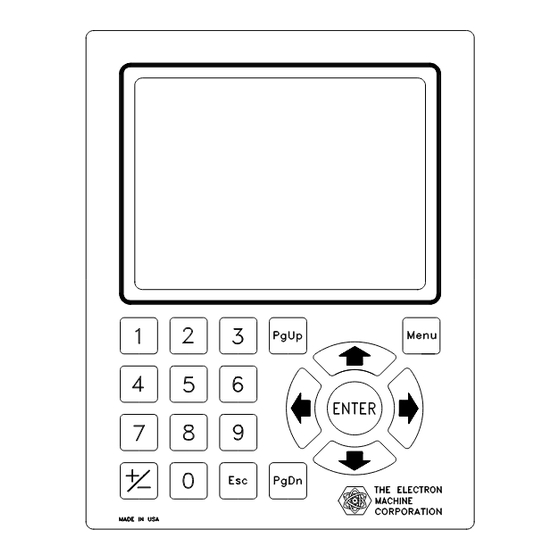
OPERATION Operation This equipment is designed for continuous operation and may be left on for extended periods of time. The Operator's Panel The Operator’s Panel or Front Panel consists of a display and a 20-button touch pad which form the interface between the operator and the instrument. The display consists of a 640 x 480 pixel TFT LCD screen which provides the operator with various messages. -
Page 12: Button Touch Pad Function Chart
OPERATION 2.1.2 Button Touch Pad Function Chart Scrolls cursor horizontally to the left and also used to initiate editing of calibration voltages in the calibration table, and temperature values in the compensation table. Scrolls cursor horizontally to the right and also used to initiate editing of all system parameters excluding those accessed by the LEFT ARROW. -
Page 13: Measurement Signal Graphing For The Mpr E-Scan
OPERATION 2.1.3 Measurement Signal Graphing for the MPR E-Scan Graph Mode Screen The MPR E-Scan offers a graphical mode display, which can be accessed from the normal mode of operation via the PgDn button on the front panel switch matrix. PgUp will then return to the normal mode display. -
Page 14: Normal Mode
Note: In normal mode set points cannot be changed or adjustments made. 2.2.2 System Indicators Isolation valve is closed. The MPR E-Scan will not initiate a prism clean. Below min purge temperature limit. No prism clean allowed. Measurement Hold. Current readings and analog outputs are maintained until complete. -
Page 15: The Menu Options In Normal Mode
OPERATION 2.2.3 The Menu Options in Normal Mode Normal mode is entered by default, upon power up. To gain access to other system features select the MENU button on the Front Panel Touch Pad. Note: The screen names and setpoints below are just an example, they will vary from application to application Normal Mode Screen with Menu Options When the MENU button is... -
Page 16: Overview Of Menu Options
OPERATION 2.2.4 Overview of Menu Options PRODUCT option allows the operator to select a product from a list of previously calibrated products. When a new product is chosen, all operating parameters are automatically loaded so that the E-Scan can immediately be ready to measure the “new” product selected. This menu option also allows the operator to enter actual product names which are attached to associated product numbers. -
Page 17: Product Selection
OPERATION PRODUCT SELECTION Product Selection P Product Screen The product menu displays the current product selected, a list of all available products, and three menu options: “Get”, “Store”, “Name”. Using the Front Panel buttons the operator can highlight and then select specific menu options. - Page 18 OPERATION PRODUCT SELECTION The second menu option, “Store”, allows the operator to create a new product by selecting a product number that will be the destination for the current product calibration and configuration information. When the “Store” option is selected, the following is displayed: Store Mode Screen The product menu options have been replaced by the “Store Mode”...
- Page 19 OPERATION PRODUCT SELECTION Using the Front Panel buttons, product 03 can be selected which would result in the following display: Name Mode Alphabet Screen This is the product name mode alphabet menu. It displays the current product selected in the upper left corner, the alphabetic characters available for assigning a product name in the center, and the product name at the bottom which is...
-
Page 20: Calibration Selection
OPERATION ALIBRATION Calibration Selection Calibration Mode Screen The calibration menu contains four menu options: 1. Limits - This option contains the system limits for alarms, purge cycle, analog output, filter weight, measurement scale and offset. 2. Meas. - This option allows entry to the calibration measurement routine. - Page 21 OPERATION CALIBRATION Measurement Alarm High: If the measurement exceeds this limit, a system alarm is activated. An error message will appear in the status window in normal mode, and the high measurement alarm relay will be turned on. Measurement Alarm Delay: This is the alarm delay time in seconds for the process measurement that must expire while a limit is exceeded before an error is activated.
- Page 22 OPERATION CALIBRATION Temp. Anlg. Min. Output: This is the temperature reading that will produce a 4 mA (optional) or 0 volt output. Temp. Anlg. Max. Output: This is the temperature reading that will produce a 20 mA (optional) or 10 volt output. Filter Weight: This is a value that controls system response time to process measurement changes.
- Page 23 OPERATION CALIBRATION An example of what is displayed while calibrating Sample #1 is shown below: Calibration Sample Example Screen At this point, sample #1 should be on the sensing head, and a sample value should be entered. When the ENTER button is selected, the measurement voltage displayed at the bottom is put in the table as the measurement...
- Page 24 OPERATION CALIBRATION The final option of the calibration menu is “Anlg. 0" which activates the following display: Analog Zero Adjustment Screen The analog zero is used to adjust the displayed reading to agree with customer testing methods. analog zero function can be thought of as a fine zero adjustment of the measurement reading, whereas the R61 potentiometer on the sensing...
-
Page 25: Configuration Selection
OPERATION ONFIGURATION Configuration Selection Configuration Screen The configuration menu contains eight menu options. 1. Features - This contains system feature options that configured by the operator such as purge/hold and smart cleaning. 2. Head - This configuration option is password protected and is to be used by EMC technicians only. - Page 26 OPERATION CONFIGURATION The first configuration option, “Features” activates the following display: Configuration Features Screen Purge/Hold allows the system to work with a purge interface and also allows all readings to be frozen or placed on hold. Both menu options can be selected from normal mode. The purge option can also be activated by the automatic purging cycle defined by the purge cycle time...
- Page 27 OPERATION CONFIGURATION The next available configuration menu option “Decimal” activates the following display: Decimal Setup Screen The decimal place option allows the operator configure various measurement readout formats. When selected, all measurement readings as well as calibration limits will reflect the chosen format. The format chosen will depend on the resolution desired by the operator.
- Page 28 EMC software installed to establish communications. The PC software is a statistical analysis package that can be used to monitor up to 4 on-line MPR E-Scan units. 2. Baud Rate - Is the selectable transmission rate for the communications.
- Page 29 OPERATION CONFIGURATION The final configuration menu option is “Alarms”. When selected, it activates the following display: Configuration Alarms Screen There are two alarm options. 1. Meas. Alr. - The process measurement alarms configured as High/Low, Low/Low, High/High, Deviation/Setpoint, and No Meas. Alarms. High/Low Alarm - An error occurs if the process measurement falls below a low limit or exceeds a high...
-
Page 30: Print Selection
OPERATION PRINT SELECTION Print Selection Print Mode Screen The print menu consists of three options 1. Calib & Config - This option will print calibration information including system limits, calibration table, temperature compensation, analog zero adjustment. It will also print out all system configuration information. -
Page 31: Diagnostic Selection
OPERATION IAGNOSTIC ELECTION Diagnostic Selection Diagnostic Mode Screen The Diagnostics menu contains the following options: 1. Voltages - This displays all pertinent system voltages such as: measurement voltage, temperature voltage, and lamp voltage. 2. Relays - This allows the operator to toggle system relays for testing or troubleshooting purposes. - Page 32 OPERATION DIAGNOSTIC SELECTION The “Relays” option activates the following display: Diagnostic Relay Screen There are eight total relays, two of which are used for custom inputs. The other six relays are activated when either measurement or temperature alarms are occurring or when purging. Using the Front Panel buttons, all relays can be tested by toggling the output...
- Page 33 OPERATION DIAGNOSTIC SELECTION Finally, the “Time/Date” diagnostic option activates the following display: This menu enables the operator to set the system time and date. System Time: This is the time displayed in military format in normal mode. System Date: This is the date displayed in normal mode.
-
Page 34: Offset Selection
OPERATION OFFSET SELECTION Offset Selection Offset Mode Screen Selecting “Offset” from normal mode activates the offset line in the calibration limits menu, which is visually highlighted by the edit cursor in the offset value field. This enables operator make adjustments to the measurement reading in order to “zero in”... -
Page 35: Purge Selection
OPERATION OFFSET SELECTION Purge Selection Purge Mode Screen Selecting the “Purge” option from normal mode adds purge information to the current display and starts the purge cycle. When purging, the “H” system indicator (measurement hold) displayed to the far right of the displayed reading, measurement voltage as well as the... -
Page 36: Hold Selection
OPERATION HOLD SELECTION 2.10 Hold Selection Hold Mode Screen When the “Hold” option is selected from normal mode, the “H” system indicator is added to the right of the displayed reading. This option allows the operator to freeze system readings and analog output at any time using the Front Panel buttons. -
Page 37: Problem Analysis
PROBLEM ANALYSIS Problem Analysis Procedures The following analysis procedures are meant to aid in isolating E-Scan failures down to the board, or in the case of the sensing head--device level. Board or device replacement with a fast turnaround is available from EMC. (See “Repair/Replacement Policy”) These abbreviations are used: Main E-Scan I/O board Conditions analog voltages for digital microprocessor. -
Page 38: Trouble Shooting Chart
PROBLEM ANALYSIS Trouble Shooting Chart SYMPTOM POSSIBLE CAUSE No display, failsafe LED off. Fuse blown. No display, backlighting Power supply failure, check 15vdc and 5vdc. No display and failsafe LED on. Display failure. Video cable failure. Display on but is garbled CPU card failing. -
Page 39: Service
Service EMC Warranty The Electron Machine Corporation warrants that the equipment manufactured by EMC is free of defects in material and workmanship. Should such fault appear within two years of date of shipment from our factory, the Electron-Machine Corporation will repair or replace the defective part upon its prepaid return to Umatilla, Florida USA. -
Page 40: Spare Parts
All orders will receive prompt attention. Phone: (352)-669-3101 Fax: (352)-669-1373 E-Mail: sales@electronmachine.com 4.4.2 Available Spare Parts Description Catalog # MPR E-Scan Door Assembly w/Electronics 511010 Sensing Head E-Scan 511002 O-Ring 03-030 Viton pkg of 10 (other materials 596405 available) Fuses –... -
Page 41: Preventive Maintenance
SERVICE Preventive Maintenance The MPR E-Scan requires very little maintenance, but should be checked periodically for proper working conditions. We suggest that the measurement, temperature, and lamp voltages be checked every month in the diagnostics mode and recorded on the log sheet or copy of the sheet at the end of this section. -
Page 42: Maintenance Log Sheet
SERVICE Maintenance Log Sheet Measurement Temperature Lamp Desiccant Date Time Voltage Voltage Voltage Color Initials... -
Page 43: System Information
MATION NFOR System Information Technical Description 5.1.1 Sensing Head The MPR E-Scan uses an LED as a light source and utilizes state of the art CCD (charge coupled device) technology to accomplish scanning the reflected light returned from the prism. -
Page 44: Ccd Linear Array
MATION NFOR 5.1.1.2 CCD Linear Array The linear array used in the E-Scan includes 3648 individual photo sites. Each of these photo- diodes independently measures the incident radiation between scan intervals and stores an electrical charge which reflects the measured intensity. At the end of this interval the shift gate is activated and the charges are simultaneously transferred into the shift register. -
Page 45: Console
MATION NFOR P to P voltage - LED current control Filtered CCD Signal 5.1.2 Console The console is constructed of molded fiberglass polyester to give protection in harsh environments. 5.1.2.1 Display The LCD (liquid crystal display) has a pixel count of 640 by 480 to give very sharp resolution with LED backlighting. -
Page 46: Cable Entry And Mounting
MATION NFOR 5.1.2.3 Cable entry and mounting The E-Scan console is set up to be mounted to a wall or other mounting device by the bracket located on the bottom of the console. This also serves as a cable and power entry plate. It is possible to change out the console without removing any wiring from the connectors. -
Page 47: Cpu Card
The processing power of the MPR E-Scan is performed by the microprocessor on the CPU core module. The layout for this card, with standard cable connections, is shown on the above figure for the CPU card layout. -
Page 48: Supplemental Card Information
MATION NFOR 5.1.2.8 Supplemental Card Information Additional cards may be used for special features and options. -
Page 49: Refractometer Specifications
MATION NFOR Refractometer Specifications Accuracy +/-0.0002 R.I. min (typ. 0.1% by weight) to 0.000075 R.I. max Span 0.0015 R.I. minimum (1 Brix) 0.214 R.I. maximum (100 Brix) Repeatability Corresponds to accuracy Sensitivity Corresponds to accuracy Stability No recorded drift over 24 hour period Response time console 250m.s. - Page 50 MATION NFOR - N O T E S-...
- Page 51 QUICK REFERENCE GUIDE MPR E-Scan MENU PRODUCT NOTE: Up to 99 ranges available. Can select from 1 to 99 different products. Store Allows creation of 1 to 99 different products. Name Used to name each product (1-99 ranges). PRINT Will print out all Calibration, Meas., Temp.
- Page 52 Meas. Used to calibrate unit. Can use up to 30 samples. Selected when Temp. Compensating the E-Scan or wanting to Temp. modify the table. (see manual before attempting). Used as a zero adjust, centered at 2047. Will have a range of 1433 - Anlg O 2661 or 3.00 volts of meas.
- Page 53 Comm. Setup Choose between STD. Comm., PC Comm. Old, and PC Comm. New. Baud Rate Select between 9600, 4800, 2400, 1200 Band. Unit No. Configure unit for PC Communications. Initialize Password protected. Used for system initialization. Change between resolution of measurement units - xx, xx.x, xxx.x, Decimal xx.xx, x.xxxx, xxx.xx formats available.
-
Page 55: Drawings List
Assembly MPR E-Scan Interface Board B-11366 Schematic E-Scan Interface Board B-12699-1 Assembly MPR E-Scan I/O CPLD Card (Two Sheets) A-12698 Schematic Diagram MPR E-Scan I/O CPLD Card (Six Sheets) B-13024 Assembly, Analog Conditioning Board B-13025 Schematic Diagram, Analog Conditioning Board A-11792...
Need help?
Do you have a question about the MPR E-SCAN and is the answer not in the manual?
Questions and answers