Table of Contents
Advertisement
Quick Links
Advertisement
Table of Contents

Summary of Contents for Impax 2000
- Page 1 2000 Supervisor’s Guide...
- Page 2 IMPAX monitoring systems. It is assumed that the software in the IMPAX 2000 is versions 48 or 58. If you are not sure not sure of the software version in your IMPAX 2000 unit please refer to chapter 8 in the Supervisor’s Guide.
-
Page 3: Table Of Contents
3. Setup and Operation Getting Started, Setting up new job Clearing Counters Clearing Tolerance/Errors Starting a New Job Tolerance Setup Machine Operation 4. IMPAX Information Displays Quantity Displays Tolerance Displays Error Displays Force Displays Backstroke/NoFeed Limilts 5. Tolerance Setting Guide 6. - Page 4 Specifications Back view of Control Console Satellite Circuit IMPAX Control Console...
-
Page 5: Introduction And Theory Of Operation
(due to tool breakage, material variation, machine problems, etc.) The forces required to form the part also change. IMPAX can be set up to detect a variety of changes and stop the machine before further damage or waste occurs. - Page 6 Another device, the machine position sensor, is turned on by a timing cam when it is time for the part to be formed, at that time, the IMPAX monitor measures the impulse from each force sensor. This measurement is converted to a number and stored in memory.
-
Page 7: Description Of Controls
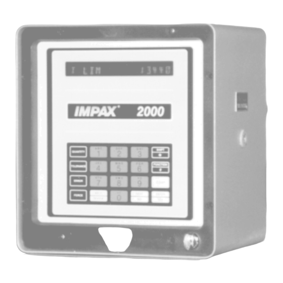
Chapter 2 - Description of Controls The IMPAX monitor is comprised of several components which are interconnected by wiring. All components are mounted on the forming machine except for the IMPAX Control Console which is isolated on its own pedestal. -
Page 8: Control Console
The function buttons may operate differently depending on the position of the key switch. If the key is removed, IMPAX will only display information. If the key is inserted, the Keypad can be used for programming and diagnostics. -
Page 9: Setup And Operation
5. The desired number of exceptions, which let-by a small percentage of “bad” parts (this feature may also be omitted). Setting up the IMPAX unit for a new job may be done any time before beginning the job, by anyone who has a Supervisor’s Key... -
Page 10: Clearing Tolerance/Errors
If you do not wish to do this, press Next/No. If you desire to, press Enter/Yes. IF YOUR ANSWER IS YES: IF YOU HAVE AN IMPAX 2000, the Enter/Yes PROD CLEARED display will show “CLEAR EXCEPTIONS”. -
Page 11: Starting A New Job
Error CLEAR ERRORS? The display will show “CLEAR EXCEPTIONS?”. Press Enter/Yes to Enter/Yes ERRORS CLEARED clear the record of the Exceptions. In the IMPAX 2000, the display will now show: CLEAR EXCPT? Enter/Yes EXCPT CLEARED... -
Page 12: Tolerance Setup
“COUNTS SET.” CHANNEL 1 ? If any tolerances need to be set, IMPAX reminds you to continue by displaying Note: There is a way to change the piece counts “CHANNEL 1 ?”... - Page 13 Setting Tolerances: You will be asked to give a tolerance Will Show number to each measuring channel. This value controls how closely that station is to be monitored. (Refer to page 23 of this guide) The display now shows “CHANNEL 1 CHANNEL 1 ? ?”, asking for a tolerance number for the first station.
- Page 14 “CUMU” stands for cumulative. This Enter/Yes (Next option or channel) means that IMPAX will allow a certain number of errors out of 100 to be ignored. For example, if I set the Once all tolerances, fixed limits, excpts, nofeeds,...
- Page 15 Setting Tolerances - cont. For example, if I set the number to 2, IMPAX would allow 2 errors in a row but the 3rd error in a row would cause the machine to stop. When tuning the IMPAX unit, it is often helpful to set a large number of exceptions, say 10 or 15 and watch the force values in the Error/Exceptions buffer.
-
Page 16: Machine Operation
Setting Tolerances - cont. The next display will be “PLUS 1/ 0000.” The number entered here (0-9999) will allow a Special Exception for 1 machine cycle per each group of x cycles the machine runs without feed. Example: If the number programmed here is 100, nd the machine runs 600 cycles without feed, the forces will be allowed outside normal limits during the first 6 machine cycles during which the feed is again detected. -
Page 17: Impax Information Displays
Chapter 4 - IMPAX Information Displays Useful information is available from the IMPAX console simply by pressing buttons. This may be done whether the machine is running or stopped. Unless otherwise instructed, the Supervisor’s Key should be removed or turned to the vertical position while performing these steps. -
Page 18: Tolerance Displays
“CHANNEL 1 5(?)”, then the tolerance X can be from 0 to 9, or *. setting for channel 1 is set to 5. --You will know which tool the IMPAX unit is referring to by the display: ex. “STATION 1” or “BLOW 1”. - Page 19 X is the tolerance setting for channel Y that channel 2 is set for tolerance level 8 X can be from 0 to 9, or *. but should be set lower. IMPAX is suggesting that it would run on a tolerance of 6.
-
Page 20: Error Displays
Error Displays (messages are for example only): Press Display Will Show If there have been no errors since the errors were Press Error. If there have been no last cleared problems since the job began (or since Error NO ERRORS the Error display was last cleared,) the display will show “NO ERROR”. -
Page 21: Force Displays
Press Next/No. The display now shows numbers, such as “101*157*150 6(3)”. This shows the force measurement which caused the IMPAX to stop the numbers are for example only machine. Note that the middle number must always be either above the upper... - Page 22 The middle number may change with every stroke; the other numbers will change most when IMPAX first ‘learns.’ These numbers are devised by IMPAX based on the average force value and the tolerance number entered for that channel.
- Page 23 Another useful force function is the *. Typically IMPAX multiplies the force measurements by a scale factor. If you wish to see the actual measurements instead of the scaled numbers, press the * button while looking at the force display.
-
Page 24: Backstroke/Nofeed Limilts
Backstroke and Nofeed Limits: Press Display Will Show To see the Backstroke limit, press (only for threadrolling applications) Force then 9 (Minimum/Maximum (numbers are for example only) settings), then 9 again. This will Force C2 105*125*150 display “018*128*002”. The first number, 018, is the Backstroke High Limit, the middle number, 128, is the C2 M 120*128*136... -
Page 25: Tolerance Setting Guide
Look at the force display to see how close the limits have been set. When the IMPAX begins to stop the machine and no problem is found, ‘back off’ by raising the tolerance setting. Check the force display occasionally to be sure the force limits are as close as they can be;... - Page 26 One problem with Auto-Tolerance is that if the forming process becomes inconsistent very gradually, IMPAX may ‘track it’ and not catch the problem. You should set the tolerances manually after the job is running well; the Auto-Tolerance numbers may be used as a guide.
-
Page 27: Troubleshooting And Service
Uniformity. Run header; observe forces and parts Produced. Check for loose tooling. IMPAX fails to stop header when problems Tolerance is set too wide of set to zero. Enter occur; smashups, breakage, dropped parts. lower tolerance number. Supervisor’s Key is in Green light stays on. -
Page 28: Simple Repairs
There are two fuses located on the back panel of the IMPAX console. If the power is on but the displays do not light up, check the 3 amp fuse. If the display comes up but the monitor won’t count or the force measurements do not come up,... - Page 29 First, turn off the IMPAX console and pull the plug for safety. Using a Phillips screwdriver, remove the screw which attach the front panel of the console. Gently tip the front panel outwards. Disconnect the white power supply plug from the front panel circuit board by pressing in the two latches on its sides and pulling it out.
-
Page 30: Initial Installation
Position Sensor Replacement or Adjustment: If IMPAX will not count parts although the machine is running in green, the problem is related to the position sensor. The simplest problem is that the cam or flag which passes in front of the sensor to actuate it, may be damaged or missing. - Page 31 In some cases, existing machine wireways may be used (shared). 110 volt power for the IMPAX console should not be derived from the machine power, but should be an isolated circuit known to be free of electrical interference, surges, and drops due to motor loads.
- Page 32 Connection to Machine Electrical Cabinet: In order to stop the machine, several wires must be run from the Satellite Box to the machine electrical cabinet or control panel. These wires must be inside a conduit. Sensor Connections: Wires from the Position and Force sensors must be returned to the Satellite Box. Although it is not strictly necessary that they be inside conduits, it is advisable to do so for the physical protection of the delicate wires.
-
Page 33: Customer Service
If you have a problem which cannot be fixed by any of the procedures in this book, do not hesitate to call IMPAX for service. Often, the problem can be fixed by simple instructions over the telephone. Before calling, be sure you know all of the facts and symptoms of the problem, information about the model and program revision numbers of the IMPAX unit, and the make and the model of the header, roller, or other machine which it controls. -
Page 34: Programming
Chapter 7 - Programming for the IMPAX 2000 Introduction This section is provided as a guide to the IMPAX Version 58 software. It is not intended to replace training, but rather to guide the user through changes they may choose to make in the options available in the IMPAX Versions 58 Software. -
Page 35: System/Fault Procedures
Whenever the power to the IMPAX CPU is interrupted, you will see a display “SYSTEM FAULT”. This can happen whenever there is a power surge or if the IMPAX unit is taken apart and the front panel is disconnected from the power supply. -
Page 36: Basic Information/Function #'S
This section is actually the definition of how the IMPAX interacts with the machine. See the section on Relay Definition for more details. Function #6 will send you to the Timers Area. See the Section on Timers for more information. - Page 37 If the number you have entered does not match the IMPAX unit’s access code, the display will show “ACCESS DENIED” for a few seconds, followed by the production counter. If the display shows “LOAD STD PRGM?”, you have entered the correct access code, and you may now check and/or modify the unit’s Channel Definition.
- Page 38 IMPAX unit interact with a threadroller by allowing the IMPAX to detect a part stuck to the die during the backstroke. If not detected by IMPAX, such a condition could damage the tooling. Press Next/No to select between the two choices, then press Enter/Yes to lock it in.
- Page 39 “CONS” stands for consecutive. This means that IMPAX will allow a certain number of errors in a row to be ignored. For example, if I set the number to 2, IMPAX would allow 2 errors in a row but the 3rd error in a row would cause the machine to stop. When tuning the IMPAX unit, it is often helpful to set a large number of exceptions, say 10 or 15 and watch the force values in the Error/Exceptions buffer.
- Page 40 (16) strokes and that is called the “Medium Count Limit”. Lastly, the IMPAX monitor can compare the learned value to the average value of the last sixty- four (64) strokes and that is called the “High Count Limit”. It is possible to disable the limits for this channel by blanking out the letters SLMH.
- Page 41 Entering Channel Names The keypad of the IMPAX 2000 with Version 58 software allows the entry of alphanumeric characters for defining software channel names, and for the entry of tags (or identifiers) to be used with IMPAXNET.
-
Page 42: Machine/Relay Defintion
Press the numbers of your access code; the display shows a “*” for each digit pressed. After you have pressed the four digits, press Enter/Yes. If the number you have entered does not match the IMPAX unit’s access code, the display will show “ACCESS DENIED” for a few seconds, followed by the production counter. -
Page 43: Setting The Timers
The display will now say “SET TIME?” If you wish to set the clock in the IMPAX unit, press the Enter/Yes key. The display will now show one of the days of the week, I. e. Tuesday. The Next/No key can be used to toggle between the seven days of the week. When you select the correct day, press the Enter/Yes key. - Page 44 Next/No key. Setting the Data Communication Parameters The next display will show “SET DATA COMM?” This step is only used if the IMPAX unit is to be connected to the IMPAXNET Data Communications software. The first step is to press the Enter/Yes key.
- Page 45 Setting the Test Count Test Count is the number of cycles to be made in Test Mode before the IMPAX unit shuts off the machine. This feature is used for the operator to jog the machine while setting up the job. The IMPAX unit does not count parts while it is in this mode.
- Page 46 SHOP ORDER NUMBER. This completes the entry, unless you want to enter more tag labels. Once this is done, you can go to Function (#) 9 and the IMPAX unit will display SHOP ORDER NUMBER. You press the Enter/Yes key and then enter the appropriate number. The IMPAX unit will date/time stamp this entry and it can be uploaded to a Personal Computer, if this IMPAX unit is attached to IMPAXNET.
- Page 47 4. Relay Disabled means that you do not want to use this particular relay for this application. Once you have selected the type of relay you want this relay to be, press the Enter/Yes key. If you selected MODE CHNG RELAY, the next display will show “RELAY ON ????.” The question marks can be a combination of the letters STPL.
-
Page 48: Diagnostics
Press the number 9 key. If the display shows _ _ _ _ _ _ _ _ _ _ _ _ _ _ _, there is nothing being transmitted or received by the IMPAX unit via the IMPAXNET. If the display has characters on... - Page 49 Press the number 1 key. The display will show “VERSION XXXXX-XX”, the X's reference the software version that is in the IMPAX system. Press Enter/Yes. The display shows “P-X TH-YY D-ZZ”. X refers to the software language in the IMPAX: 0 is English 1 is German...
- Page 50 Press the number 3 key. The display shows “BYPASS IMPAX?”. Press the Enter/Yes key. (Note: When the IMPAX is bypassed there is no machine protection.) The display will show two or three four digit characters, these four digit characters are the checksums of the software loaded into EPROMS on the CPU board.
- Page 51 Signal Strength and Amplification Values Press the number 8 key. The display shows “BYPASS IMPAX?”. Press the Enter/Yes key. (Note: When the IMPAX is bypassed there is no machine protection.) The display shows “C1 XXPYY XXIZZ”. C1 is the current channel, blow, station..that you are looking at.
-
Page 52: Specifications And Drawings
Power Requirements: 115 volts at 1 amp or 230 volts at ½ amp, 50/60 Hz AC. IMPAX is protected against surges and motor interference. Dimensions: Satellite Box: 8" H x 6" W x 4" D Control Console: 11-3/4"... - Page 53 DRAWINGS Backview of the Control Console...
- Page 54 Satellite Box Circuitry...
- Page 55 IMPAX 2000 Control Console...
Need help?
Do you have a question about the 2000 and is the answer not in the manual?
Questions and answers