
Summary of Contents for Ubiquiti SM-MI-250
- Page 1 INSTALLATION and OPERATION USER and OPERATION USER MANUAL MANUAL UBIQUITI SM-MI- -250 MICROINVERTER PVP-0001 Ver1.2...
- Page 2 P a g e Contact Information 2580 Orchard Parkway San Jose, CA 95131 http://www.ubnt.com/contact/ info@ubnt.com PVSupport@ubnt.com FCC Compliance This device complies with Part 15 of the FCC Rules. Operation is subject to the following two conditions: (1) this device may not cause harmful interference, and (2) this device must accept any interference received, including interference that may cause undesired operation.
-
Page 3: Table Of Contents
Safety Symbols ............................. 3 Safety Instructions ..........................3 ABOUT UBIQUITI MICRO INVERTERS ..............5 General Overview ..........................5 Advantages of UBIQUITI Micro Inverters .................... 5 TECHNICAL SPECIFICATIONS ........................ 6 BEFORE INSTALLATION ....................7 Layout PV System ..........................7 Compatibility and Capacity ........................7 Utility Service Requirements ....................... -
Page 4: Important Safety Information
(such as co-located antennas transmitting the same information) is expressly forbidden. WARNING! Be aware that even without an external voltage source connected, the SM-MI-250 micro inverter may contain high voltages and there is a risk of electrical shock. WARNING! Connect the UBIQUITI micro inverter to the utility grid only after receiving prior approval from the electrical utility company. - Page 5 DANGER! Do not disconnect the DC power source from the UBIQUITI micro inverter without first disconnecting the AC power source. Both AC and DC power sources must be disconnected before servicing. Be aware that DC power/voltage is generated when the photovoltaic array is exposed to light.
-
Page 6: About Ubiquiti Micro Inverters
SM-MI-250 converts DC power (generated by the solar module) to AC power (powers your home appliances). The UBIQUITI micro inverter is installed on the back of each solar module; and connects directly to the electric utility grid without the need for a string or central inverter. The AC output from SM-MI-250 micro inverter is synchronized and in-phase with the frequency range and voltage of the electric utility grid. -
Page 7: Technical Specifications
P a g e TECHNICAL SPECIFICATIONS INPUT DATA (DC) Recommended input power (STC) 210 - 300 W Maximum input DC voltage Peak power tracking voltage 22 - 36 V Operating range 16 V - 45 V Min/Max start voltage 22 V / 45 V Max DC short circuit current 15 A Max input current... -
Page 8: Before Installation
Compatibility and Capacity UBIQUITI SM-MI-250 micro inverters are electrically compatible with PV modules that have a voltage range of 22 ~ 36V and a maximum input power of 300W. For more information, refer to the Technical Specifications section on page 16. - Page 9 EGC grounding process is completed via the grounding connection of SM-MI-250 4-wire AC cable to the AC trunk cable. Despite the fact that UBIQUITI has made it easier for the SM-MI-250 to install, by integrating the ground to the AC trunk cable, the PV module will still need to be grounded according to the PV manufacturer’s recommended...
-
Page 10: Ac Cable Terminal Connector
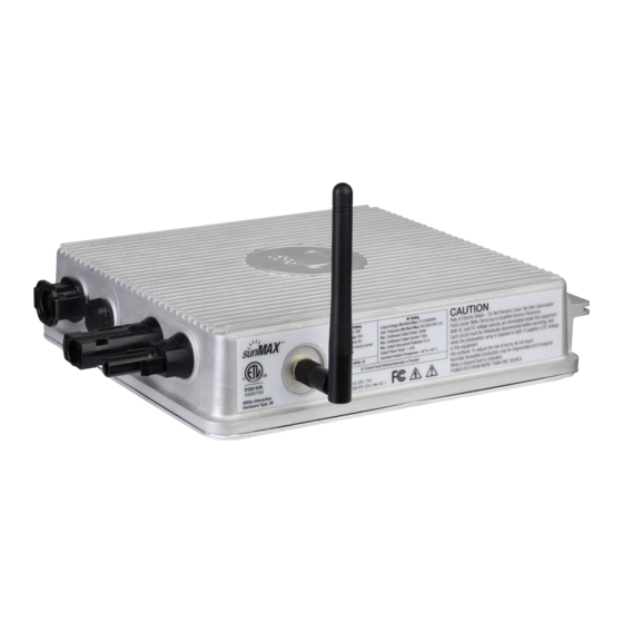
P a g e Antenna antenna type : Type: A antenna gain : 3 ±0.5 dBi antenna connector : SMA straight jack/Reverse, Gold-plated AC Cable terminal connector The connector as below picture is for cable terminal connection. Installer could connect it with general electrical power cable, and please follow the color for identifying of phase, neutral and ground connection. -
Page 11: Ubiquiti Sm-Mi-250 Installation Procedure
| 10 UBIQUITI SM-MI-250 INSTALLATION PROCEDURE The following section list steps on how to install the UBIQUITI SM-MI-250 micro inverter onto PV module. Before installing, review and follow all important safety instructions listed in this section: Step 0: Please ensure you have all the components mentioned as below. - Page 12 P a g e | 11 Step 3: Arrange and fasten the cable. Step 4: Plug DC connector into MI. Step 5: Complete all modules following by step 0 to Step 4 before roof installation. Step 6: Combine Male and Female connector between AC modules.
- Page 13 P a g e | 12 Step 7: Locate the open connector at the end of your array of AC Modules and connect the end run cable to the Y-Cable until it is firmly seated. (Note: One End Run Assembly can support up to 16 continuous AC Modules in an array.
- Page 14 P a g e | 13 Step 9: Position the end run assembly underneath and inline with the outside edge of the AC module preferably with the conduit side connection facing downhill. Step 10: Review the layout and check the voltage range again. Voltage between red wire and black wire should be closed to 240V.
- Page 15 P a g e | 14 There are some optional materials/accessories for different installation requirements, users could evaluate and count the quantities by below sheet. Catego ry Catego ry Item Item Q'ty Q'ty No te No te Catego ry Catego ry Item Item Q'ty...
- Page 16 WARNING Do not attempt to repair this product; it does not contain user-serviceable parts. Repairs and internal servicing should only be performed by UBIQUITI authorized service personnel. Commissioning and Operating Turn on the AC disconnector or the circuit breaker of each micro inverter string.
-
Page 17: Important Notification
When a Ground fault occurs, the GFDI will trigger the LED light to flash in alternating Orange and Red colour, and SM-MI-250 will automatically disconnect all the conductors as a safety precaution. If GFDI has been detected, please contact with the installer and follow the Operation Manual to fix this situation. - Page 18 P a g e | 17 Disconnect the grounding wire or washer from the micro inverter. Remove the micro inverter from the PV racking. WARNING Do not leave the disconnected SM-SP-250W module and expolse connectors for an extended period of time.
- Page 19 P a g e | 18 Manufactured by: UBIQUITI 2580 Orchard Parkway San Jose, CA 95131 Tel: http://www.ubnt.com USA Office: UBIQUITI 103A Pioneer Way, Mountain View, CA, 94041 Tel:...
Need help?
Do you have a question about the SM-MI-250 and is the answer not in the manual?
Questions and answers