
Summary of Contents for Advanced Flight Systems AF-5400
- Page 1 AF-5000 Pilot’s Guide Experimental instrument limited to use in experimental aircraft. Not approved for use in aircraft with FAA type certificates. Patents 6,271,769 B1 and 6,940,425...
-
Page 2: Af-5000 Series Post Installation Check
AF-5000 Series Post Installation Check CAUTION: Do not fly the aircraft until the following check list has been completed. Never Power the system with an automotive battery charger and the aircraft battery disconnected. Before Power is applied for the First Time ✓... - Page 3 First Engine Start ✓ With relay protection diodes installed, your AFS screen(s) can be turned on before the engine is started. ✓ After the engine has started, verify oil pressure and temperature. If none is indicated SHUT DOWN the engine. Verify all wiring and consult your local A&P, the engine manufacturer, and/or AFS technical support.
-
Page 4: Limited Warranty / Agreement
LIMITED WARRANTY / AGREEMENT Advanced Flight Systems Inc. (“AFS”) warrants its aircraft monitoring system instrument and system components to be free from defects in materials and workmanship for a period of one year commencing on the date of the first flight of the instrument or one year after the invoice date, whichever comes first. -
Page 5: Table Of Contents
EFIS Display Layout ..........................19 Screen Selection ................................19 EFIS Button Options ..............................21 ENGINE Button Options ............................... 21 MAP Button Options ..............................22 AF-5400 Interface ................................ 23 Touch Screen ................................25 Altitude ..................................26 Barometric Pressure/Altitude ............................. 26 Airspeed ..................................26 Horizon Roll and Pitch .............................. - Page 6 Display Configuration Menu ........................ 45 EFIS Navigation (HSI) ........................... 46 CDI/BRG Source Selection ............................47 GPS Navigation Display ..............................48 VOR Navigation Display ............................... 49 ILS Navigation Display ..............................50 Autopilot Control / Flight Director ....................... 51 Autopilot Operation ..............................51 Dynon SV-Autopilot Gain Settings ..........................
- Page 7 Wi-Fi Adaptor ............................ 101 Configuring the Wi-Fi Adapter ........................... 101 Connecting AF-5000 to ForeFlight ..........................103 Send and Receive Flight Plans with ForeFlight ......................104 Logbook Interface..........................106 Synthetic Appraoch ........................... 107 Engine Monitor Display ........................108 Fuel Computer ................................108 Fuel Computer Modes ...............................
- Page 8 MANUAL REVISION HISTORY REVISION DATE DESCRIPTION 1/6/2012 Updates 2/1/2012 Updated Schematics, Software Updates, Map data 2/2/2012 Audio, GTN650 2/7/2012 Landing Gear, ARINC Schematics, Rotax Wiring 4/1/2012 New VFR & IFR Low Chart Format, Serial Schematics 6/20/2012 Landing Gear Warning, Remote AHRS, GTN650 VFR Sectionals, IFR Low, Radio, Transponder, Airplane Icon 8/7/2012 Vendor Logo...
-
Page 9: Introduction
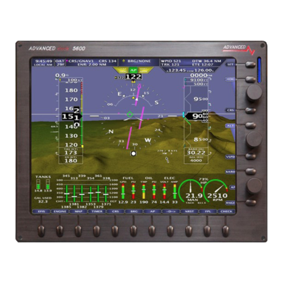
AF-5500 use an 8.4” display. The AF-5600 uses a 10.4" display and the AF-5800 and AF-5700 use a 12.1" display. The AF-5400 fits in the same mounting cut-out as the AF-3500/4500 EFIS making it extremely easy for those wanting to upgrade. Each... - Page 10 WARNING It is possible for any instrument to fail and display inaccurate readings. Therefore, the pilot must be able to recognize an instrument failure and must be proficient in operating the aircraft safely in spite of an instrument failure. Contact the FAA or a local flight instructor if training is desired to be proficient.
- Page 11 Attitude Calculation The AF-5000 artificial horizon display (attitude) is generated via a complex algorithm using a multitude of sensors as described in Table 2. In normal operation an AF-5000 uses airspeed to provide superior attitude accuracy. Should airspeed become unavailable due to inadvertent blockage of the pitot system, GPS ground speed will be used as an attitude aid.
- Page 12 The SV-KNOB-PANEL is an optional panel-mounted module for AF-5000. This control panel has three knobs dedicated to the most common AF-5000 bug functions – ALT, BARO, and HDG/TRK. This module is particularly useful in AF-5400 systems. Note that these bugs can also be adjusted from the three AF-5000 display knobs.
- Page 13 External Controls, Indicators, Jacks, etc. The primary harness for each AF-5000 display provides inputs or outputs for external buttons, switches, indicators, jacks, etc. Some of these are required (such as Servo Disconnect / CWS), while others provide optional additional functionality. As part of your familiarization with your AF-5000 system, you should identify these additional controls on your panel or elsewhere in your cabin, and how they interact with your AF-5000 system.
-
Page 14: System Operation
SYSTEM OPERATION Turning the Unit ON The AF-5000 Series will turn on anytime power is applied to the main power input and will stay running as long as there is power supplied. If power from the aircraft hot battery bus or backup battery is connected to the backup power input, the system can be turned on by pressing and holding button 1 (lower left button) for 2 seconds. -
Page 15: Efis Screen Menus
EFIS Screen Menus The EFIS boots in the MAIN screen menu and will automatically time out and return to it from the sub menus. In the MAIN screen menu, the knobs on the right control the function that the flag is pointed to. In this picture the top knob is controlling the Heading Bug. - Page 16 SET > EFIS Page Settings HDG BUG Turns ON/OFF Heading Bug ALT BUG Turns ON/OFF Altitude Bug IAS BUG Turns ON/OFF Airspeed Bug HDGC:G Sets the color of the EFIS DG / HIS Gray White G RESET Resets the G Meter AOA CAL Enter AOA Calibration Mode SOURCE...
-
Page 17: Check Menu
CHECK Menu Pressing the [CHECK] button brings up the Checklist Page. You use the joystick to move between Checklist items and press in to check off the item. The CHECKLIST page has the following buttons and menus Side Buttons BACK Returns to the Main Menu Dims the displays in the Aircraft BARO... -
Page 18: Screen Hardware Reboot
Screen Hardware Reboot The display CPU can be rebooted by pressing and holding (Button 1) and (Knob 1) for 40 seconds. This causes the internal hardware to reboot and reinitialize the system. This should only be required if the EFIS failed to load the software. -
Page 19: Efis Display Layout
EFIS Display Layout Screen Selection The first three buttons on the screen bottom row [EFIS], [ENGINE], [MAP] control what is displayed on the EFIS screen. There are additional options available for each item that pop up when the button is pressed. The button layout is configured so that a double press of the button always changes the item from (OFF to ON) or (ON to OFF) for simplified operation. - Page 20 Screen Selection using Touch Gestures A single finger touch and drag with longer than 1 inch of travel will cause the screen to change views as described below: A single finger swipe in the downward direction will cause a screen in full engine view to minimize to half engine view. A screen in half engine view will change to no engine view.
-
Page 21: Efis Button Options
EFIS Button Options [OFF] Turns the EFIS Horizon OFF [ANALOG] Turns the EFIS Analog 6 Pack display ON [EFIS] Turns the EFIS Horizon ON [OAT F/C] Selects Outside temperature display to Fahrenheit or Celsius [FD ON/OFF] Turns the Flight Director ON or OFF [HITS ON/OFF] Turns the Highway In The Sky ON or OFF [AOA ON/OFF/DCL]... -
Page 22: Map Button Options
MAP Button Options [AIRPORT] Displays the Flight Guide Airport Diagram (Requires optional data subscription) [AP PLT] Displays the Approach Plate (Requires optional data subscription) [OFF] Turns the MAP display OFF [MAP] Displays the standard MAP screen [SECTION] Display the VFR Sectional (Requires optional data subscription) [IFR LOW] Display the IFR Low Altitude Chart (Requires optional data subscription) [SOURCE]... -
Page 23: Af-5400 Interface
AF-5400 Interface The 5400 Interface is very similar to the standard AF-5000 series. All AF-5400 displays are equipped with a touch screen interface to allow for equal functionality with fewer buttons and knobs. The right side button tags are all touch controlled, as is the keyboard for data input. - Page 24 Changing Knob Function (Baro, ALT, Zoom…) 1. Press Knob 2. Twist knob to scroll through Menus Press Knob again to set new function Access the [SET] Menus/Calibration Page on 5400 Display 1. Tap [SET] 2. The SET categories (EFIS, ENGINE…) will be displayed across the buttons. 3.
-
Page 25: Touch Screen
Touch Screen Touch Screen equipped displays provide a multitude of interface control and input options for nearly every display function. User interface gains simplicity and ease of use through taps, swipes, drags and pinches. Areas boxed in yellow recognize a tap input to adjust parameters and as a shortcut to menus. For instance, a tap of the Transponder Status tab in the top left will bring up the transponder control page. -
Page 26: Altitude
Altitude The altitude tape gives a visual representation of altitude. The digital readout points to current altitude, thousands of feet are displayed using large numbers while hundreds of feet are displayed using smaller numbers. The green chevrons are located at 1000’ intervals for IFR cruising altitudes and the white chevrons are located at 500’... -
Page 27: Heading - Efis Dg
Heading – EFIS DG This heading is displayed like a standard slaved directional gyro. The digital readout in the pointer shows the current heading. If the EFIS DG is red, the heading should not be relied on and the magnetometer wiring should be checked. -
Page 28: Skid/Slip Ball (Inclinometer)
Skid/Slip Ball (Inclinometer) The skid/slip ball works like any standard mechanical gauge. If the ball is within the black lines, the aircraft is in coordinated flight. The ball on the outside of a turn indicates a skid, while the ball on the inside of a turn indicates a slip. -
Page 29: G-Meter
G-Meter The AF-5000 has two G Meter options, one on the left side of the airspeed tape or a round G-Meter that can be configured to pop up at G Warning. You can also select a G Meter for the left or right inset window. -
Page 30: Flight Path Marker
Flight Path Marker The green flight path marker (FPM) or velocity vector shows where the aircraft is actually moving. Think of it as a visual representation of GPS Track. The green target will only be centered under steady state flight conditions with no wind. Usually the target will be moving around the display showing where the airplane is going, not where the nose is pointed. - Page 31 MDA/DH Alerting The MDA Alerting function provides visual and voice “MINIMUMS” alerts when approaching the Bug. • Upon passing through 100 feet of the Selected Altitude, the Bug changes from Cyan to White. • After reaching the Selected Altitude the Bug changes from White to Yellow, and the voice alert “MINIMUMS”...
-
Page 32: Clock/Timer Operation
Clock/Timer Operation The system time is automatically set by GPS. The unit will set Zulu time automatically when GPS signal is acquired. Clock Setting Touch the Time or press the [TIMER] button to enter the date/time adjustment menu. Press the [OFFSET] button to enter the Time Zone offset from UTC time (i.e. - Page 33 Dual AHRS Monitoring If a system has two ADAHRS units the EFIS screen will constantly compare both ADAHRS units for a mismatch error in Roll, Pitch, or Heading an AHRS MISMATCH error will be displayed on the center of the screen. You can select the ADAHRS that the system is using from the OPTIONS MENU (Touch the center of the PFD display).
-
Page 34: Angle Of Attack (Aoa)
Angle of Attack (AOA) See Appendix I: AOA Pressure Port Location The EFIS can display an AOA if the optional AOA system is installed. An in-flight AOA calibration is required before the AOA indication can be deemed reliable. The AOA in-flight settings can be adjusted from following Menu: [EFIS] ->... - Page 35 EFIS AOA LANDING CONFIGURATION CALIBRATION CALIBRATION AIRCRAFT LOCATION ....AIRBORNE CHECK LIST FLAPS/GEAR ....CONFIRMED DOWN EFIS_cklst.doc 09/2014 rev 4 EFIS AOA DISPLAY ON........ON paper color Green AOA CAL Button ....... PUSH/RELEASE CONFIRM ......1OL flap down calibrate page POST INSTALLATION PRE FLIGHT ZERO “G”...
-
Page 36: Analog Instrument Page
Analog Instrument Page [EFIS] [ANALOG] [SET] [EFIS] [ANALOG] AF-5400 Version 15.0 AF-5000 Series Pilot Guide... -
Page 37: Tcw Backup Battery
TCW Backup Battery When the main power to the EFIS is lost the EFIS should continue to run on the battery backup power. A new fully charged battery should power the EFIS for about an hour. You should dim the EFIS screen (CHECK > DIM >... -
Page 38: Synthetic Vision
Synthetic Vision Synthetic Vision (SVN) displays a forward looking perspective of the terrain ahead. This includes mountains, rivers/waterways, obstacles, and runways. The Synthetic Vision database requires current Map Data, found on the AFS website. The Synthetic vision database is stored on the USB stick in the HRTERRAIN folder. Note: Having synthetic vision changes the way the attitude indicator behaves;... -
Page 39: Terrain Awareness And Warning System (Taws)
Synthetic Vision Settings Enable/Disable - [SET] -> [EFIS] -> [SVN] (green is on, dark blue is off) Instrument Calibration: Synthetic Vision 1. Synthetic Vision ON/OFF - Enables/Disables SVN (if the software key is installed) 2. Altitude Source - (AUTO, GPS ONLY, BARO ONLY) - Selects the altitude source for SVN. Default is AUTO. -
Page 40: Svn Taws Settings
SVN TAWS Settings 1. Synthetic Vision (ON/OFF) Turns OFF the Synthetic Vision feature. 2. Altitude Source Source for SVN (should be auto) 3. Terrain Warnings ON/OFF Enables/Disables terrain shading based on altitude 4. TAWS Airspeed Shutoff (KTS) Airspeed that the terrain warning colors turn OFF 5. -
Page 41: Obstacle Display
Obstacle Display SVN shares the same obstacle database as the top-down map page. Obstacles are shown at their proper height above ground and at their bases are drawn at half of their height. There are several exclusions users will want to be aware of: - Obstacles beyond 18nm are not shown - Obstacles less than 1000ft AGL are not shown beyond 6nm - Obstacles more than 2,000ft AGL below the aircraft are not shown... -
Page 42: Traffic Display
Traffic Display When a device capable of receiving traffic information is installed and configured, traffic can be displayed within the Synthetic Vision display to improve situational awareness. Traffic 7 NM and Climbing Traffic 6 NM Traffic more than 9 NM •... -
Page 43: Highway In The Sky (Hits)
Highway in the Sky (HITS) Any EFIS system with Synthetic Vision is capable of displaying Highway in the Sky (HITS). HITS is the artificial generation of boxes that direct the pilot towards a programmed navigation course set by the GPS. HITS is depicted as magenta boxes in the synthetic vision. -
Page 44: Options Menu
Options Menu You select the EFIS OPTIONS menu by touching the center of the PFD page. The Options menu provides a quick way to get to frequently used items. ADAHRS Selection Selects the current ADAHRS to use. In AUTO mode the system will switch ADAHRS units if one fails. -
Page 45: Display Configuration Menu
Display Configuration Menu You select the display setup menu by pressing the [DISP] button from the EFIS main menu or by pressing the back-arrow icon. The Display Menu controls how the screen is split between EFIS, Engine and Mapping. Version 15.0 AF-5000 Series Pilot Guide... -
Page 46: Efis Navigation (Hsi)
Bearing Needle Info EFIS Navigation (HSI) Course Needle Info Waypoint Info To/From Waypoint Identifier CDI Needle The EFIS can display an HSI when connected to a Nav radio, GPS, or GPS Navigator. The system has two main navigation needles; Course and Bearing. The navigation source can be individually selected for each. If an separate Nav Radio is connected, a second bearing needle can be displayed when the standby Nav frequency is enabled. -
Page 47: Cdi/Brg Source Selection
CDI/BRG Source Selection The CDI or BRG source is selected by touching the label Or pressing the CDI button You can switch between the CDI and BRG Tab by touching the Tab or using the Joystick (LEFT <> RIGHT) SOURCE Selects the needle source GNAV1 GPS Navigator... -
Page 48: Gps Navigation Display
GPS Navigation Display CRS (Course) Flight Phase LNAV: L/VNAV: LNAV+V: LPV: APR: Vertical Deviation/Glide Path TRM: Indicator ENR: Full Scale CDI TO/FROM CDI Needle Vertical Deviation/Glide Path Indicator The Glide Path Indicator (GPI) can be displayed from a WAAS GPS and is analogous to the glideslope for GPS approaches supporting WAAS vertical guidance (LNAV+V,L/VNV, LPV) NOTE: Requires an IFD440, IFD540, GTN-650/750, GNS-430W/530W, along with an ARINC adaptor module. -
Page 49: Vor Navigation Display
VOR Navigation Display OBS Setting VOR Frequency To/From Indicator The Green course indicator points to the current course selected using the OBS setting. The OBS setting can be set using the right upper knob on when [CRS] is active (press the button below the top knob if CRS is not active). The current OBS setting is displayed in the upper CRS/BRG information boxes. -
Page 50: Ils Navigation Display
ILS Navigation Display AP/FD Mode APP CRS (OBS) Lateral Vertical ILS Frequency Localizer CDI Glide Slope VDI Always set the ILS inbound Approach Course (APP CRS) using the CRS knob selection. If the radio is tuned to a standard ILS frequency and is giving a valid indication, the display will show in green letters. -
Page 51: Autopilot Control / Flight Director
Autopilot Control / Flight Director Current AP Mode AP Status Lateral Vertical Engaged Engage/Disengage AP Button Flight Director On/Off Button The Integrated Advanced-SV Autopilot utilizes the SV-Network servos and is commanded by, and controlled through the EFIS Display. The optional Autopilot Interface Panel adds autopilot auto trim, and dedicated physical control buttons. - Page 52 HDG Mode In Heading mode the autopilot will make the aircraft’s magnetic heading follow the Yellow colored heading bug on the HSI. When you select Heading mode the HSI heading bug color will change to Yellow. Magnetic Heading ARM Mode In ARM mode the autopilot will follow the heading bug on the HSI until the CDI needle is less than 80% deflection and the heading is within +/- 30 deg of the CDI Needle.
- Page 53 ALT - IAS Mode In ALT – Indicated airspeed mode the autopilot will make the aircrafts altitude follow the Teal colored altitude bug. When you change the altitude bug the autopilot will climb or descend following the Yellow Airspeed Bug. You can change the Airspeed Bug using the SET >...
- Page 54 VFPL Mode In Flight Plan mode the autopilot will follow the waypoint altitudes set in the Flight Plan Menu. If the waypoint does not have an altitude set it will continue to follow the Altitude Bug. The autopilot will not descend below the Altitude Bug, the EFIS will prompt you if you need to lower the Altitude Bug setting.
-
Page 55: Dynon Sv-Autopilot Gain Settings
Dynon SV-Autopilot Gain Settings The Dynon SV-Autopilot settings can be adjusted from the SET > CAL > Autopilot menu when not flying or you can adjust them from the SET > AP/FD screen menu. SET > CAL > AUTOPILOT SET > AP/FD Menu Roll AXIS Overview This procedure tunes the roll autopilot servo and thus, the flight characteristics of the aircraft in heading holds and turns. - Page 56 If the AP is slow to respond to the TRK changes, increase the ROLL AXIS SENTIVITY and watch for improvement. In some cases this may require a fair amount of increase, but be cautious about changing it too quickly. Sensitivity adjustments alone may not completely eliminate overshoot. If increasing sensitivity no longer improves performance, ROLL GAIN may be used to fine tune the roll axis.
- Page 57 Pitch AXIS Overview The goal of tuning IAS Hold is to give the AP the best possible pitch axis performance. Crisp speed control is a prerequisite for good altitude and glideslope control. The procedure which follows can be used both for initial tuning and for troubleshooting problems which may arise in your system.
- Page 58 Flowchart Pitch Axis – IAS Hold Procedure Version 15.0 AF-5000 Series Pilot Guide...
- Page 59 Pitch AXIS Hold and Capture Overview Both holding and capturing altitude are related but distinct parts of the autopilot. The Altitude Hold Procedure which follows will address common problems, and once those are resolved, direct you to the Altitude Capture Procedure, which will tune your system to capture and hold vertical speed and capture altitude targets without overshoot.
- Page 60 Altitude Capture Procedure (Part 1 of 2) Part 2 of 2 Version 15.0 AF-5000 Series Pilot Guide...
- Page 61 Turbulance Tuning Procedure Overview Once you have configured your autopilot to capture and hold airspeeds and altitudes, you may wish to adjust the ride quality in turbulence, particularly on the glideslope. In general, the autopilot will attempt to maintain a constant G-loading through bumps by pulling or pushing G to oppose G generated by "air pockets".
- Page 62 Autopilot Settings – Defaults Version 15.0 AF-5000 Series Pilot Guide...
-
Page 63: Efis Flight Director
EFIS Flight Director The flight director is turned on and off using the FD button. The wings that come up when the flight director is enabled will show the aircraft positioning to follow. All the pilot has to do is keep the triangle in the wings as they move to follow the commanded source. -
Page 64: Trutrak Autopilots
Trutrak Autopilots The AF-Pilot, Sorcerer, Vision and Gemini have the following modes controlled from the buttons on the face of the autopilot. [AP] - Autopilot control mode. Pressing the AP button will cause the autopilot to turn on and follow the current ground track and the current vertical speed of the aircraft. - Page 65 Changing Autopilot Mode using the Joystick If you are using a Trutrak autopilot and you have the AP configured for Joystick controls in the CAL > Autopilot menu, the joystick can also be used as a shortcut. LEFT and RIGHT cycle between Lateral modes while UP and DOWN cycle through Vertical modes.
-
Page 66: About Page
ABOUT Page Pressing the ABOUT button from the Checklist page will bring up information about the system. You can touch a tab to select it or use the joystick to move between tabs. System – MAP – Weather – Transponder – GPS SYS Information Displays the system Serial Number, software version information, IP address MAP Information... -
Page 67: Wx Information
WX Information The WX information page contains information and diagnostics for any installed XM or ADS-B receiver. XM Weather Information (USA and Canada) ADSB Weather Information Version 15.0 AF-5000 Series Pilot Guide... -
Page 68: Transponder Information
Transponder Information The XPNDR information page contains information about the Transponder GPS Information The GPS information page contains information about the attached GPS units. Version 15.0 AF-5000 Series Pilot Guide... -
Page 69: Electronic Circuit Breaker Page
Electronic Circuit Breaker Page The Electronic Circuit Breaker menu gives you the ability to see the current state of each electronic circuit breaker and reset any of the tripped breakers. You can also turn ON or OFF any of the outputs using the screen buttons. -
Page 70: Maintenance Page
Maintenance Page You bring up the Maintenance Page by pressing the CHECK > MAINT button. You can update the date of any of the maintenance items by selecting the item using the joystick and then pressing the [UPDATE] button. To edit the maintenance items, you will need to do the following: •... -
Page 71: Radio / Transponder / Audio Panel Controls
Radio / Transponder / Audio Panel Controls The Radio and Transponder controls are selected by pressing the [SET] button in the upper right hand corner of the screen. Press XPDR for the Transponder controls Press COM for the Comm radio controls Transponder Code Standby Radio Frequency Transponder Mode... -
Page 72: Com Radio Control
Com Radio Control The Com radio remote interface supports the Dynon Com Radio, IFD540, GNC255, SL30, SL40. The radio page has three tabs (RCNT, COM, FREQ) You move between the tabs using the joystick or touching the tab. COM Tab Selects the Ground Freq Selects the Tower Freq Adjust Volume (if supported) - Page 73 FREQ Tab RCNT Tab Version 15.0 AF-5000 Series Pilot Guide...
- Page 74 Using the TWR, ATIS, GND, and ATC Buttons When an airport is loaded on the radio, press the TWR, ATIS, GND, and ATC buttons to send frequencies associated with that airport to the standby frequency. Repeated presses of these buttons will cycle through all available frequencies of that type (for example busy airports may have multiple tower frequencies): TWR: Tunes tower, Unicom, and Multicom frequencies.
-
Page 75: Transponder Control
Transponder Control Access the Remote Transponder interface through [SET] [XPDR] or by touching the transponder status readout in the top left corner of the screen. The remote transponder has the following controls. AUTO Turns transponder mode to Automatic Turns Transponder ON with no Altitude reporting STBY Sets Transponder to Standby Mode Turns transponder ON in Altitude reporting mode IDNT... -
Page 76: Remote Audio Panel Control
Remote Audio Panel Control Audio Panel Interface The AF-5000 has the ability to remotely control a PS Engineering remote audio panel (PDA360EX-R or PAC15) through the touch screen, and/or hardware buttons. To bring up the Audio Panel Control page: • Select buttons [CHECK] ... - Page 77 Selecting Nav Radios On screen touch or hardware buttons can be used to select one of the NAV Radios. When the system is monitoring a NAV radio a green bar will be displayed on the NAV radio button. USB Charging Jack The front panel USB-type connector is available for charging devices, such as iPad or cell phones.
- Page 78 Music Muting The SoftMute™ circuit will mute the music whenever there is conversation on the radio, the intercom, or both, depending on the “Mute” mode selected. When that conversation stops, the music returns to the previous level comfortably, over a second or so. The mute mode functions are controlled through Music Mute Menu which has three modes for each music input.
- Page 79 Internal Recorder and playback The PDA360EX comes equipped with an internal recorder. This digital system stores the last incoming audio from the radio you have selected for transmit. It can store as many of 8 incoming messages, and up to 45 seconds of audio.
-
Page 80: Moving Map Display
Moving Map Display Current Waypoint GPS Track METAR Symbol Zoom Range Class D Airspace Major Road Map GPS Source Map Features Currently the map will display the following features: 1. Public and Private airports 5. State Lines 2. Airspace 6. Rivers 3. -
Page 81: Map Options
The moving map can be displayed as a partial screen along with the EFIS and/or Engine Monitor or as a complete page. Users can also select the airspeed and altitude tapes to be displayed on the map from the [SET] [MAP] menu and selecting the [AIRDATA] buttons. EFIS, MAP , ENGINE Map Page with Air Data ON Map Options... -
Page 82: Zoom Range
Zoom Range The current zoom range is displayed by an arc on the top of the map display with its current digital range. The zoom range can be adjusted using the joystick anytime [RNGE] is active. The map software will progressively declutter airports, intersections and obstacles from the screen as the range is increased. -
Page 83: Remote Efis Joystick Control
Remote EFIS Joystick Control If the PFD screen does not have a map displayed you can use the joystick to control the remote EFIS screen map. If the PFD does have a map displayed the joystick will control the local map. You need to configure the MFD EFIS to allow joystick control from the PFD display: SET >... -
Page 84: Nearest Airport
Nearest Airport Pressing the [NRST] button from the main menu will bring up a sorted list of the nearest 16 airports displayed on the screen at the current zoom level. To display the actual closest airports, zoom in before pressing the [NRST] button. The joystick is used to select the desired airport. Pressing the [INFO] button will display the information for the highlighted airport. -
Page 85: Emergency Airport Button
EMERGENCY Airport Button After pressing the [NRST] button it changes to the EMERGENCY button (i.e. Double Tap [NRST]). Pressing this button will bring up a list off all airports that are within engine out gliding range. You need to configure the following items in calibration for your specific aircraft: Version 15.0 AF-5000 Series Pilot Guide... -
Page 86: Airport Info
Airport Info Pressing the [-D->] button from the menu will bring up multiple pages of airport info, including runways, frequencies and airport information. The pages are selected by dragging the joystick in the direction of the desired page. Airspace Airspace is displayed on the moving map. Airspace Information, including the vertical boundaries, is selectable through the Map Pointer. -
Page 87: Selecting Charts
Selecting Charts Switching between MAP, Sectional, IFR Low, IFR High, Airport diagrams, and Approach Plates can be done through a simple selection of the [MAP] Button, which will then bring up the menu to select the desired database/chart. Selection through the Touch Screen is done by tapping the screen in any open area, then pressing the desired map ICON. -
Page 88: Vfr Sectional
VFR Sectional Full Screen Mode Split Screen Mode Version 15.0 AF-5000 Series Pilot Guide... -
Page 89: Ifr Low Altitude Chart
IFR Low Altitude Chart Airport Diagrams Version 15.0 AF-5000 Series Pilot Guide... -
Page 90: Ifr Approach Plates
IFR Approach Plates The EFIS can display an IFR approach plate if you have the optional Seattle Avionics Chart data. The Seattle Avionics data is stored on the system USB memory stick plugged into the back of the unit. The approach plates are geo-referenced and will display current aircraft position (if on the approach plate area). -
Page 91: Map Weather Data Display
Map Weather Data Display You can display weather data on the map and sectional from our XM Weather receiver or ADS-B receiver. The EFIS can also display ADS-B weather from a portable Wi-Fi enabled weather receiver that transmits using standard GDL90 data. CAUTION: NEXRAD weather data should only be used for long-range planning purposes. - Page 92 NEXRAD LIMITATIONS • NEXRAD base reflectivity does not provide sufficient information to determine cloud layers or precipitation characteristics. There is no distinguishing factors between wet snow, wet hail, and rain. • NEXRAD base reflectivity is sampled at the minimum antenna elevation angle. An individual NEXRAD site cannot depict high altitude storms at close ranges.
- Page 93 Winds Aloft Winds aloft are displayed over the map page using standard NOAA barbed symbols. To change the altitude, press [MAP] -> [WX] and use the joystick to select Flight Level. Altitudes are given in Flight Levels (i.e. FL120 is 12,000ft) To enable/disable Winds Aloft press [MAP] ->...
- Page 94 XM Data Service Once subscribed to an XM service plan, an activation signal will need to be sent while the EFIS and XM module are powered on (usually for about 15 minutes). The AF-5000 will display the following items from the “Aviator”...
- Page 95 ADS-B Data Service When connected to an SV-ADSB module, The EFIS can display NEXRAD weather and Temporary flight Restriction (TFR) information visually on the map or sectional page. Additionally, textual METAR and TAF weather reports are available for airports that report such information. The SV-ADSB receives traffic and weather via the 978 MHz UAT ADS-B frequencies, which are only utilized by the FAA’s ADS-B system.
- Page 96 ADS-B Receiver Status / Data Age Current Regonal and Conus data age is displayed on the upper left hand corner of the map. REGNL is the local high-resolution data and CONUS is the low resolution data for the continental US. The EFIS >...
-
Page 97: Map Traffic Display
Map Traffic Display WARNING: Traffic information displayed on the Map is provided for visually assisting in acquiring other aircraft. The aircraft should be maneuvered based only upon ATC guidance or positive visual acquisition of conflicting aircraft. Traffic 200ft below Traffic 800ft above and descending Traffic direction and 2 minute arrow... -
Page 98: Efis Database Files
• TIS: Traffic provided from an SV-XPNDR-261/262, Garmin GTX 330, or any other device that is configured to output traffic information in the Garmin TIS format. The EFIS is receiving traffic data from the device which is providing traffic to the best of its ability. EFIS Database Files The moving map navigational database files are stored in internal EFIS memory. -
Page 99: Internal Flight Planning
Internal Flight Planning The AF-5000 Series EFIS systems have an internal flight planning feature, eliminating the requirement for an external GPS to provide flight plan waypoints. Only a basic GPS with NMEA data output is required to utilize this feature (though it can still be used with any GPS navigator as well). -
Page 100: Direct-To
Direct-To Proceeding Direct-To an intermediate waypoint: Use the cursor to highlight the waypoint to proceed to, press the [DIRECT] button. The EFIS will then sequence to the selected waypoint. Fly-Leg The Fly-Leg features is used to fly a leg between two intermediate waypoints. For example, a flight plan has A, B, C, and D intersections before the destination and the pilots wants to skip A and fly the leg between B and C (an airway). -
Page 101: Wi-Fi Adaptor
Wi-Fi Adaptor The Wi-Fi Adapter for AF-5000 allows supported devices and third-party applications to interface with an AF- 5000 EFIS. The Wi-Fi Adapter supports ForeFlight Mobile connectivity to AF-5000 on both iPads and iPhones. The Wi-Fi Adapter plugs into a USB port and must be plugged into the EFIS display before power on and remain plugged in for the full flight. - Page 102 Client Mode Use Client Mode if you want the EFIS to connect to a Wifi ADS-B Module that supports GDL90 data or a Wi-Fi Hotspot. Wi-Fi Hotspot EFIS data updates will be added in a future software update. After changing the Wi-Fi mode you will need to power down and power up the EFIS for the changes to take effect.
-
Page 103: Connecting Af-5000 To Foreflight
Connecting AF-5000 to ForeFlight AF-5000 and ForeFlight customers can send and receive flight plans between AF-5000 and their ForeFlight Mobile app on Apple iPad, iPhone, and iPod Touch devices running the iOS operating system. The AF-5000 will also transmit its GPS position and ADAHRS information to ForeFlight for use within the ForeFlight app. -
Page 104: Send And Receive Flight Plans With Foreflight
Send and Receive Flight Plans with ForeFlight Once you have your flight plan set up in ForeFlight on your iOS device (iPad or iPhone), you can send it to AF-5000 EFIS Flight Planning page and Moving Map. The EFIS CDI source (Flight Plan) must be set to Internal to accept a flight plan from ForeFlight. - Page 105 • Once AF-5000 EFIS receives the flight plan a confirmation message will appear on the EFIS and the Flight Plan will be in the EFIS Flight Plan window. The flight plan can then be used and edited on the AF-5000 EFIS. To have ForeFlight retrieve the AF-5000 EFIS flight plan, simply touch the Panel button at the top of the app window.
-
Page 106: Logbook Interface
Logbook Interface [CHECK] [LOGBOOK] The AF-5000 Series EFIS systems have an internal, and exportable, Log Book feature. The Log Book will store information about your flights, including Duration, Landings, Date, Departure Airport, and Arrival Airport. To Export Logbook data from your AF-5000 insert a SD Card and press [SET] [LOGS] [LOGBOOK] This information is easily imported to LogbookPro on your personal computer. -
Page 107: Synthetic Appraoch
Synthetic Appraoch With the AF-5000 series EFIS you can setup a Synthetic Approach to any airport in the map database or user airport data file with runway endpoint data. The flight plan menu lets you select the runway and set the glideslope. -
Page 108: Engine Monitor Display
Engine Monitor Display The system can display the engine monitor on the bottom of the main EFIS page or as a full Engine page if the system has one of the following: 1. The screen has an engine monitor board installed in the case. 2. -
Page 109: Fuel Computer Modes
Fuel Computer Modes The fuel computer display can be set to display any of the following by pressing the [FC MODE] button. The mode label will be if the fuel computer gallons remaining amount does not match the fuel tanks. Gallons Used ->... -
Page 110: Power Display
The pilot can add or subtract fuel to the computer by pressing [FC ADJ] and using the keypad or rotating the joystick for the correct amount and then pressing the [FC SET] button. % Power Display The system will display the estimated %Power and the current (RICH-PEAK-LEAN) Status You need to select the correct engine type and horsepower in the calibration menu for the Horsepower to display. -
Page 111: Egt/Cht Display Modes
EGT/CHT Display Modes Cylinder Head Temperatures (CHT) Exhaust Gas Temperatures (EGT) All cylinders are continuously displayed in both analog and digital formats. The cylinders are laid out sequentially with cylinder #1 on the left followed by cylinder #2 to its right and so on. -
Page 112: Efis Checklists
EFIS Checklists To view checklists pages press the [CHECK] button from the main screen. Rotate the joystick to scroll through the checklists. To return to the main screen press the [BACK] button. If the [CHECK] button is pressed the page that is displayed is controlled by the following: ENGINE RPM PAGE... - Page 113 CHKLST2.LINE5, Flight Instruments - SET CHKLST2.LINE6, Altimeter - CORRECT PRESSURE CHKLST2.LINE7, Fuel Selector Valve - DESIRED TANK CHKLST2.LINE8, Mixture - RICH (below 3000ft) CHKLST2.LINE9, Elevator and Aileron Trim - NEUTRAL CHKLST2.LINE10, Throttle -- 1800 RPM CHKLST2.LINE11, ...Magnetos - CHECK (175 max drop) CHKLST2.LINE12, ...Prop - CHECK OPERATION To restore the checklist file to the EFIS perform the same steps above but instead press [REST] Version 15.0...
-
Page 114: Maintenance Log
Maintenance Log The system has an Aircraft Maintenance Log that can be setup to track any number of user configurable items. Each item can be configured as a Tach time or calendar time controlled event. Once the time interval has expired the item will turn red indicating the need for service. -
Page 115: Weight & Balance Screen
Weight & Balance Screen The Weight & Balance page is selected from the following menu: [CHECK] -> [W&B] The middle knob is used to select the station to adjust. The joystick is used to adjust the weight/qty at the selected station. The Weight &... -
Page 116: Efis Data Logs
EFIS Data Logs The EFIS data logs can be downloaded using the USB or SD data card from the SET > LOGS Menu. SYSTEM System diagnostic file SCN SHOT Screen Captures (Press and Hold the button below the joystick to capture the screen LOGBOOK Logbook Files APLOGS... - Page 117 Using Savvy Analysis to display the recorded Flight Data https://www.savvyanalysis.com The AF-5000 recorded Flight Data is compatible with Savvy Analysis Version 15.0 AF-5000 Series Pilot Guide...
-
Page 118: Appendix A: Af-5000 Ifr Procedures
APPENDIX A: AF-5000 IFR Procedures Flying an LPV Approach The following example shows how to use the EFIS and Avidyne IFD540 to fly from KEUG to KUAO using the GPS 35 LPV approach. In this picture we have entered a flight plan into the IFD540 to go from KEUG to KUAO with the middle CVO VOR waypoint. - Page 119 In this picture we have selected the RNAV GPS 35 LPV approach on the IFD540, selected EMADE as our Initial Approach Fix. The autopilot mode is NAV for Lateral and ARM for Vertical. This means the autopilot is following the IFD540's lateral GPS course and is holding altitude at the altitude bug until vertical guidance is provided from the IFD540 (usually just outside the FAF).
- Page 120 From the map screen we have selected APP PLATE, selected the RNAV 35 approach plate, and then used the knob to scroll and zoom the approach plate. The map screen will remember the current plate and scroll position making it very easy to switch back and forth from the map screen to the approach plate. From the approach plate we see that we need to be at 3700Ft between EMADE and DUBMY and we have set the altitude bug to 3700 ft.
- Page 121 • We have also set the Minimums Bug to the 450Ft Decision Height from the approach plate. The autopilot will not fly below the Minimums Altitude bug. • Before reaching the decision height we have set the Altitude bug to the 4000ft missed procedure altitude from the approach plate.
-
Page 122: Appendix B: Efis Map And Charts Database Updates
APPENDIX B: EFIS Map and Charts Database Updates AF-5000 MAP DATA The AF-5000 series stores the digital Map data on the internal EFIS memory. The data for the United States is updated every 28 days and provided free of charge on the www.Advanced-Flight-Systems.com site. -
Page 123: Af-5000 High Resolution Terrain Data
Once the AF2MAPUS.AFM file has been moved to the USB Memory Stick or SD card you can plug it back into the EFIS. The EFIS should recognize the new database and prompt to install it. You can force the EFIS to install the map data from the SET >... -
Page 124: Af-5000 Chart Data
AF-5000 CHART DATA For US customers, chart data subscriptions, including sectionals, IFR low and high en-route charts, procedure charts, airport diagrams. Unlike other databases that are stored in display’s internal drive, charts and airport diagrams, because of their large size, must be stored on a USB memory stick that remains connected to the display during use. - Page 125 Start the ChartData Manager Select AFS from the App or Device column Select your AFS_DATA removable drive. At this point you can see that the green light on US USB flash drive is connected (F:\) Select the data elements that you want to load onto your USB flash drive.
-
Page 126: Af-5000 High Resolution Terrain Data
ChartData Updates When new data is available from Seattle Avionics insert your USB flash drive into the computer running the Data Manager software. An alert will pop-up allowing the new data to be loaded onto the USB flash drive. Click Yes to update the USB flash drive and wait for the update process to complete ALL green lights next to your checked items indicates your device is READY.
Need help?
Do you have a question about the AF-5400 and is the answer not in the manual?
Questions and answers