Table of Contents
Troubleshooting

Summary of Contents for Geometrics G-882
- Page 1 G−882 CESIUM MARINE MAGNETOMETER 25919-OM REV. E Operation Manual COPYRIGHT © 2005 GEOMETRICS, INC. 2190 Fortune Drive, San Jose, California 95131 USA Phone: (408) 954-0522 Fax: (408) 954-0902 email: sales@mail.geometrics.com...
- Page 2 28 April 1992 and 93/68-EEC, Article 5 of 22 July 1993. The Technical documentation required by Annex IV(3) of the Low Voltage Directive is maintained by Christopher Leech of Geometrics Europe (address below). The authorized representative located within the Community is:...
- Page 4 (4,000 psi rating, telemetry over steel coax available to 10 operation is all parts of the world allowing sensor rotation for km). The G-882 also directly interfaces to all major Side work in equatorial regions. The shipboard end of the tow cable Scan manufacturers for tandem tow configurations.
- Page 5 0.5 to 1 nT at 30 ft (9 m) 10 lbs of iron 0.5 to 1 nT at 20 ft (6 m) The design of this high sensitivity G-882 marine unit is 1 lb of iron 0.5 to 1 nT at 10 ft (3 m) directed toward the largest number of user needs.
-
Page 7: Table Of Contents
4.5.1 A newly designed CSAZ Windows™ program is available on our Magnetometer CD and from our FTP site at ftp://geom.geometrics.com/pub/mag/Software/ (look for csaz- setup.exe). Please read the manual that is included with the program for complete instructions on how to use the CSAZ program for worldwide inclination and sensor orientation solutions. - Page 8 Final MagLog screen will look as above to provide diagnostics for system troubleshooting....................95 Voltage Calibration for Magnetometers using CM-221 Counters ..... 95 Appendix A – Optically Pumped Magnetometer Theory ......103 Appendix B – System Connection Wiring Diagrams ......... 106 Appendix C: G-882 With Larmor Output ........... 109...
- Page 9 This page intentionally left blank.
-
Page 10: Introduction
As always, we are here to support you and help you get the most out of your system, so we encourage you to call or email us with questions. Contact information: Technical support@mail.geometrics.com Salessales@mail.geometrics.com Tel: 408-954-0522 Fax: 408-954-0902 Geometrics Inc. G-882 Cesium Marine Magnetometer Page... -
Page 11: How It Works
‘T” with the long axis of the vessel. (see figure #1). The sensor is internally connected to the sensor-driver electronics and Larmor frequency counter circuit module Geometrics Inc. G-882 Cesium Marine Magnetometer Page... - Page 12 E) RS-232 cable F) MagLog Manual w/ software disk G) AC/DC power supply H) AC power cord I) DC power cord (with battery clips) J) Franzus international AC adapter plug kit. Figure 2 Accessory Kit Geometrics Inc. G-882 Cesium Marine Magnetometer Page...
-
Page 13: Nose Tow Configuration
In order to attach the tow cable to the front of the magnetometer the nose plug must be removed from the front of the nose piece. Begin by removing the top cover split-rings and linchpins and remove the top cover (Figure 4A to 4C below). Geometrics Inc. G-882 Cesium Marine Magnetometer Page... - Page 14 Next remove the nose plug cotter pin, black clevis pin and nose plug from the nose assembly as shown in Fig 5 A to C. Store these parts in a safe place as you will need them when you convert to CG tow configuration. Geometrics Inc. G-882 Cesium Marine Magnetometer Page...
- Page 15 (Fig 5 D) and remove the dummy plug. You do this by unscrewing the locking sleeves and pulling the dummy plug straight out. Do the same on the pigtail attached to the tow cable clevis termination. Geometrics Inc. G-882 Cesium Marine Magnetometer Page...
- Page 16 Make sure you bend over the cotter pin after installation! You will require a pair of pliers to make a good bend. Complete the nose tow assembly by gently pushing the connected cables into the nose cavity and reassembling the top cover. Geometrics Inc. G-882 Cesium Marine Magnetometer Page...
-
Page 17: Converting Nose Tow To Cg Tow
Next, inspect the mail and female connectors to ensure that there is sufficient silicone grease and mate the connectors, screwing together the locking sleeves to complete the connection (Fig 12 A). Then gently push the connector pair and Geometrics Inc. G-882 Cesium Marine Magnetometer Page... -
Page 18: Adjusting Handle And Orientation Weight
See Figure 12 C for completed assembly. Fig 12 A Figure 12 Final Nose Tow Configuration Fig 12 B Fig 12 C Adjusting Handle And Orientation Weight Geometrics Inc. G-882 Cesium Marine Magnetometer Page... - Page 19 Fig 13A. Fig 13 A Fig 13 B Loosen these screws to also rotate the nose. not remove the red locking strings. Geometrics Inc. G-882 Cesium Marine Magnetometer Page...
-
Page 20: Attaching The Tow Cable To The Vessel
With all of the components of a system connected, apply power by first turning the AC supply on. There is a switch next to the mains power entry connection. If DC power is used, hook up the batteries and DC cable. Connect to the junction box. Geometrics Inc. G-882 Cesium Marine Magnetometer Page... -
Page 21: Quick Start Software Guide
3.0 Quick Start Software Guide This section of the manual refers specifically to the installation and setup of MagLogLite or MagLog, Geometrics data logging and display programs. We use the terms MagLogLite and MagLog interchangeably to refer to the logging programs made by Geometrics;... - Page 22 PC printer port. In case of trouble, Customer Service at Geometrics can give you a temporary software key code to type into the computer and get you running.
-
Page 23: What Does Maglog Do
Survey Wizard which you will find listed under File on the MagLog menu bar. Click on File and then on Survey Wizard (see Figure 16 below). After the introduction screen is displayed, click “Next”. Geometrics Inc. G-882 Cesium Marine Magnetometer Page... -
Page 24: The Survey Wizard
GPS, for the magnetometer, a file for the line number, another for the Interpolator, which is the file with the actual relocated fish positions. Type in a name and click next (Figure 17). Geometrics Inc. G-882 Cesium Marine Magnetometer Page... - Page 25 Figure 17 Geometrics Inc. G-882 Cesium Marine Magnetometer Page...
- Page 26 (default 9600 baud) set it now. Otherwise the program will search for the connection. Select the type of magnetometer you have where 88x stands for all marine Geometrics Inc. G-882 Cesium Marine Magnetometer Page...
- Page 27 (power-up default parameters) are loaded from MagLog into the magnetometer CPU Flash memory. This means that you can change how the magnetometer initializes so that it will wake up with the Geometrics Inc. G-882 Cesium Marine Magnetometer Page...
- Page 28 If you do not have the calibration coefficients for your system, you may use the manual calibration facility included in MagLog. This feature is accessed from the configuration menu for the particular device and will be covered later in this manual under section 2.5.5. Geometrics Inc. G-882 Cesium Marine Magnetometer Page...
- Page 29 This is because when the ship is pointed in a direction different from the direction of travel (due to side currents) the currents also affect the position of the cable and fish system. MagLog will log common Geometrics Inc. G-882 Cesium Marine Magnetometer Page...
- Page 30 Gyro and Fluxgate Compasses for automatic correction of side currents. Contact Geometrics for more information and a case study. To use the Interpolator feature, click the button that says “Yes, I want real time layback calculation”. The Survey Wizard provides set up of the...
- Page 31 (Figure 26). We are presented with certain default “slot” line colors and plot definitions. We Figure 25 recommend that you use the Horizontal (Landscape) Geometrics Inc. G-882 Cesium Marine Magnetometer Page...
- Page 32 We recommend that you just accept these parameters as defaults for now. Again, these can be easily changed once the program is running. Figure 26 Geometrics Inc. G-882 Cesium Marine Magnetometer Page...
- Page 33 Of the two types (dot matrix and Windows™ laser/inkjet printers), we recommend the user of the Windows™ printers (see next screen, Figure 29). The reason is that while dot matrix printers Figure 28 Geometrics Inc. G-882 Cesium Marine Magnetometer Page...
-
Page 34: General Overview
Appendix A under Cesium Vapor Magnetometer Theory. Operation and FAQ The G−882 Marine Magnetometer is usually purchased with Geometrics logging software package MagLog-Lite or MagLog. Please refer to the Manual associated with this software for complete instructions regarding installation and setup. - Page 35 Each weight collar is 14lbs. To get to 100 ft (30m) depth will require 500 ft of Kevlar cable, towing at 3 knots with 1 extra 14lb collar weight. Moving to 4 knots will raise the fish to a depth of 75 feet (25m)! Geometrics Inc. G-882 Cesium Marine Magnetometer Page...
- Page 36 There are certain isotopes of cesium that are radioactive, but we do not use radioactive isotopes in cesium magnetometers. We use extremely small amounts (micrograms) of the pure elemental metal which is non-radioactive and essentially non-reactive in those amounts. E. How far can the magnetometer “see”? Geometrics Inc. G-882 Cesium Marine Magnetometer Page...
-
Page 37: Performance
Performance Geometrics G−882 magnetometer produces a Cesium Larmor frequency output at 3.49872 Hz per nT (in this text, nT refers to nanotesla or gamma or 10 gauss). Thus, in a nominal 50,000 nT field this frequency is about 175 kHz. The output of the system is a continuous sine wave at the Larmor frequency. -
Page 38: Sensor Orientation Guide
The G−882 Sensor Package consists of a sensor head and sensor electronics package joined by a cable. The electronics package contains an integral Geometrics CM-221 counter which converts the Larmor signal into a magnetometer reading in nano-Teslas. Digital data is transmitted via RS-232 to a data logging system. - Page 39 CSAZ Figure 32 Changing sensor orientation is simple. This adjustment will allow the sensor‘s optical axis roll angle to be set to any angle (typically only 0º, 45º or 90º required.) Geometrics Inc. G-882 Cesium Marine Magnetometer Page...
- Page 40 To get information about sensor orientation we suggest you use the program CSAZ available from our website and on the Magnetometer CD for complete worldwide survey recommendations. Geometrics Inc. G-882 Cesium Marine Magnetometer Page...
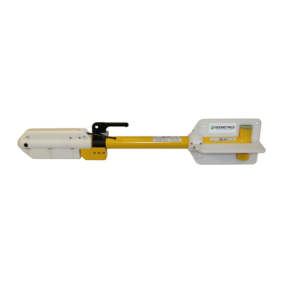
- Page 41 Keel weight Cesium sensor The G-882 Magnetometer is shown with the keel weight positioned such that the cesium sensor will tow in a position that is vertical to the surface of the earth. If an altimeter is present, the nose assembly must also be adjusted so that the altimeter is also directed towards the seabed.
-
Page 42: Main Field Inclination And Total Intensity Maps
This information is also included in the CSAZ program. Geometrics Inc. G-882 Cesium Marine Magnetometer Page... - Page 43 Figure 35 Geometrics Inc. G-882 Cesium Marine Magnetometer Page...
- Page 44 Figure 36 Geometrics Inc. G-882 Cesium Marine Magnetometer Page...
-
Page 45: Counter Data Format And Command Structure
PC are sent out the RS232 transmit pin (TxD) to the counter. Mag and other data return on the receive pin (RxD). Figure 37 MAGLOG CM-221 COUNTER Trig/Event Mark Not implemented In the G-881 Geometrics Inc. G-882 Cesium Marine Magnetometer Page... - Page 46 13-16 4 digits of A/D channel 0 (9999 full scale, 0 to +5 volts in). This channel is internal and contains the signal level of the magnetometer. an ASCII carriage return an ASCII line feed Geometrics Inc. G-882 Cesium Marine Magnetometer Page...
- Page 47 Note that only the first counter outputs a preamble character (the default character is '$'). Geometrics Inc. G-882 Cesium Marine Magnetometer Page...
-
Page 48: General Command Instructions
(and dumb terminal emulation software) can be used to control the counter output. (Dumb terminals do not normally transmit line feeds when <Enter> is pressed). 4.4.3 G−882 Quick Command list Geometrics Inc. G-882 Cesium Marine Magnetometer Page... -
Page 49: G−882 Detailed Commands
Chan. 5 28 volts at magnetometer Chan. 6 humidity inside magnetometer Chan. 7 heater Note: The depth, altimeter, and 28 volts need to have calibration coefficients applied to convert to feet, meters, or volts. 4.4.4 G−882 Detailed Commands Geometrics Inc. G-882 Cesium Marine Magnetometer Page... - Page 50 Baud rate change command 2: x MS char (1,0,0,0,0,0,0) 3: x S char (9,9,4,2,1,0,0) 4: x 3S char (2,6,8,4,2,6,3) 5: x 2S char (0,0,0,0,0,0,0) 6: x LS char (0,0,0,0,0,0,0) 7: CR carriage return Geometrics Inc. G-882 Cesium Marine Magnetometer Page...
- Page 51 Byte 1: 'D' Set the Julian day number 2: x MS digit of number ('0'-'3') 3: x 2S digit of number ('0'-'9') 4: x LS digit of number ('0'-'9') 5: CR carriage return Geometrics Inc. G-882 Cesium Marine Magnetometer Page...
- Page 52 The desired character 3: CR carriage return Jump to debug Byte 1: 'X' first char of 'XBUG' string 2: 'B' 2'cnd char 3: 'U' 3'rd char 4: 'G' 4'rth char 5: CR carriage return Geometrics Inc. G-882 Cesium Marine Magnetometer Page...
-
Page 53: Update Default Parameters
MagLogLite or MagLog program is installed and is available to check or change the magnetometer configuration and store the values in non-volatile memory. Clicking on the STORE CONFIGURATION (lower left button) sends the proper commands to the magnetometer counter board(s). Geometrics Inc. G-882 Cesium Marine Magnetometer Page... - Page 54 [Note: If it is desired to permanently save any changes to the operation parameters that may have been made, sending an UPDATE command before powering down will save them. The next time the system is powered-on the new, saved parameters will be used.] Geometrics Inc. G-882 Cesium Marine Magnetometer Page...
-
Page 55: Command Set Descriptions
This is the easiest format to view and import into various processing utilities. It is also very inefficient in terms of disk storage space and time required to transmit each cycle. There are three other output formats that can be used as well: Geometrics Inc. G-882 Cesium Marine Magnetometer Page... - Page 56 Note how easy it is to see the numbers if viewing a hex dump of the data. Remember though that it must be translated to printable characters before copying the raw data to printers or a CRT screen. Geometrics Inc. G-882 Cesium Marine Magnetometer Page...
- Page 57 The single channel Sandia format is selected with the command string "OS" or "OS0". The dual channel output is selected by the command string "OS1". Example outputs: This is the ASCII output example from earlier, but with 3 A/D channels: Geometrics Inc. G-882 Cesium Marine Magnetometer Page...
- Page 58 2C 30 30 30 34 2C 30 30 30 34 0D 0A 24 20 36 39 39 37 38 2E 33 34 37 2C 33 37 39 37 2C 30 30 30 33 2C 30 30 30 35 0D 0A Geometrics Inc. G-882 Cesium Marine Magnetometer Page...
- Page 59 - - - - - - - - - - - - - - - - - - - - - - - - - - - - - - - - - A9977813100B3749000000 A9989037600B3687000000 A9995551700B3545000000 A9999829300B3472000000 A0007883500B3329000000 (Note how the most significant '1' A0003207100B3381000000 is truncated for readings greater A9997915900B3498000000 than 100,000 nT). A8677850800B3514000000 A7877821600B3645000000 A6997834700B3797000000 Geometrics Inc. G-882 Cesium Marine Magnetometer Page...
- Page 60 Note that the "Jxxx" command only affect whether the clock increments with time. It has no effect on whether or which clock fields are output. The "OJxxxxxyy" commands selects which field are output. Geometrics Inc. G-882 Cesium Marine Magnetometer Page...
- Page 61 'Px' command is used to change it to the character sent following the 'P'. All characters are allowed except control characters, digits (0-9), spaces, commas, decimal points, and the termination char ('*'). Geometrics Inc. G-882 Cesium Marine Magnetometer Page...
- Page 62 0 responds by default). Counter 0 will modify the command string to "IJ:abcde" where the letters a-e would be replaced with an ASCII '0' (field off) or '1' (field on). The five output fields are: Geometrics Inc. G-882 Cesium Marine Magnetometer Page...
-
Page 63: Power-Up Initialization
By default all counters will wake up thinking that they are counter #0 and begin to output data at the default 10 hertz rate or as set by default parameters in flash memory. This data will appear as a synchronization command to subsequent Geometrics Inc. G-882 Cesium Marine Magnetometer Page... -
Page 64: Accessory Software
A directory called "GeoUtil" is created on the "C" drive and then all of the files are copied into that directory. After the files are copied, this batch file then runs Cm201set.bat Geometrics Inc. G-882 Cesium Marine Magnetometer Page... - Page 65 Cm201go program changes its baud rate as required. If the input line has the special code "[CLOCK]" on it, the CM-221's clock will be set to match that of the PC. A typical Cm201go.cnf would be: Geometrics Inc. G-882 Cesium Marine Magnetometer Page...
- Page 66 CM-221 which are detailed in the magnetometer manual. As an example, the command "A0000" followed by a carriage return turns off analog channel 0 (signal level) in counter 00: Each character is sent Geometrics Inc. G-882 Cesium Marine Magnetometer Page...
- Page 67 = Toggle graphics display of Mag3 on/off. Default setting is off. If turned on and no magnetometer#3 is present the Mag3 data value is forced to zero. This key has effect in graphics mode only. Geometrics Inc. G-882 Cesium Marine Magnetometer Page...
- Page 68 "Gradx" to " "GradZx" indicating the current mode. Note that this normalizing only takes place on gradient channels. <Alt F4> = Toggle true and normalized w. offset grad display. When Geometrics Inc. G-882 Cesium Marine Magnetometer Page...
- Page 69 When in graphics display mode [F5] up to six analog channels may be enabled by typing <CTRL A>. This will activate a series of questions to format the analog data for display: Display Channel Number [0-5]: Geometrics Inc. G-882 Cesium Marine Magnetometer Page...
- Page 70 As described in the magnetometer/counter manual there are 4 unipolar (including the signal level) [0 to +4.096 volts], and 2 bipolar channels [ñ 2.048 volts]. This parameter is used to signify which type of analog channel this is. Geometrics Inc. G-882 Cesium Marine Magnetometer Page...
- Page 71 : Bipolar mode, would have been set to "-" for unipolar "1000" : Full scale value. If "0000" is displayed it mean "10000" full scale. "C" : Clipped display, would be a "W" for wrap mode. Geometrics Inc. G-882 Cesium Marine Magnetometer Page...
-
Page 72: Depth Cal
4.5.4 Depth Cal This program is intended for use only if you purchased logging software other than MagLog-Lite or MagLog from Geometrics that might allow calibration of the depth sensor by determining a bias and scale factor. For additional automatic depth calibration, see Depth Calibration using MagLog-Lite or MagLog™... - Page 73 Restart your logging software and enter the bias and scale factors which were generated by the DepthCal program. Depth should now be working correctly. See example below: Depth calibration calculator Version 1.2 Note: Geometrics Inc. G-882 Cesium Marine Magnetometer Page...
- Page 74 Slope – Intercept Method Here is a method for calculating the Scale Factor and Bias for depth calibration. At the first depth, let the depth in meters be d1, and the raw reading r1. Geometrics Inc. G-882 Cesium Marine Magnetometer Page...
- Page 75 Use the INTERCEPT function to calculate the Bias. Use the SLOPE function to calculate the Scale Factor. Examples are shown in the table above. For this example, the Slope (Scale Factor) is 1.875, and the Intercept (Bias) is –56.75. Geometrics Inc. G-882 Cesium Marine Magnetometer Page...
-
Page 76: Depth Calibration Using Maglog-Lite Or Maglog
4.5.5 Depth Calibration Using MagLog-Lite or MagLog MagLog logging software from Geometrics provides capability to perform calibration of the depth sensor. It is preformed very much like the methods described above. Refer to the excerpt from the MagLog-Lite/ MagLog NTmanual below. - Page 77 Sensor #: 1 Channel #: Depth 3) Select “Auto Figure 40 calibration. You should then see the following dialog box: Geometrics Inc. G-882 Cesium Marine Magnetometer Page...
- Page 78 You need to make sure that you have at least two different depth points (e.g. it is advised to have one point near the surface, and the second point as close to the bottom as possible). Otherwise, the calibrations Geometrics Inc. G-882 Cesium Marine Magnetometer Page...
- Page 79 “Auto Calibration”.) Figure 42 You will see a dialog box: Enter your scale and bias values, and check “Channel represents depth” if this is a depth calibration. Then press “OK”. Geometrics Inc. G-882 Cesium Marine Magnetometer Page...
- Page 80 A = (Y1 Y2) (X1 X2) b = (Y2X1 Y1X2) (X1 X2) From here, we can now use these new values to calculate the correct depth, given only the pressure. Geometrics Inc. G-882 Cesium Marine Magnetometer Page...
-
Page 81: Assembly, Installation And Use
We recommend a winch if the length of the tow cable exceeds 120 m (400 ft). An on-board deck cable available from Geometrics is used to traverse the distance from the winch installation point to the logging equipment installation site. -
Page 82: Deployment Of The G−882 Magnetometer
1. Just after power-on and before the counter begins normal operation some erroneous data may be observed for a brief period of time. 2. When the counter begins normal operation the following may be observed as the magnetometer begins to warm up: Geometrics Inc. G-882 Cesium Marine Magnetometer Page... - Page 83 B. Analog channel 0, the signal level, depending on the field magnitude and sensor orientation, a normal signal could vary between 0900 and 1200. Geometrics Inc. G-882 Cesium Marine Magnetometer Page...
- Page 84 The cable may be deployed from the figure eight without knots and kinks. One person should be assigned to tend the cable on and off of the figure eight. This method is better for cable up to 120m (400ft). Geometrics Inc. G-882 Cesium Marine Magnetometer Page...
- Page 85 This will expand the Kellems and allow it to slide easily along the cable to its new position. Release the ends of the Kellems, re-anchor the end towards the towfish as shown Figure 43 and then smooth it back down along the cable towards the vessel. Geometrics Inc. G-882 Cesium Marine Magnetometer Page...
- Page 86 This graph is provided as a suggestion of what tow depths might be expected using a nose towed G−882 magnetometer. Geometrics Inc. G-882 Cesium Marine Magnetometer Page...
- Page 87 G-881 Nose Tow Depth vs Speed on a 175 ft Cable Length G-882 Nose Tow Depth vs Speed on a 175ft Cable Length Figure 44 Speed (knots) Towing a magnetometer fish from its center of gravity provides a method to allow the fish to be towed deeper, hence closer to the bottom for a better detection range.
- Page 88 G-881 CG Tow Cable Length vs Depth knots knots G-882 CG Tow Cable Length vs Depth knots Figure 1. CG TOW Cable Length in water(ft) Figure 45 Geometrics Inc. G-882 Cesium Marine Magnetometer Page...
-
Page 89: Service Information And Trouble Shooting Guide
Figures 59 and 60 show the male water tight connector on the nose bulkhead of the G−882 magnetometer. Figure 60 also shows the pin numbers for this connector. The Geometrics part number for this connector is 21-236-400. Figure 48 Figure 49 Geometrics Inc. - Page 90 Figures 48 and 49 show the female water tight connector on the wet end of the tow cable. This connector mates with the connector of Figures 50 and 51. Figure 49 also shows the pin numbers for this connector. The Geometrics part number for this connector is 21-236-410.
-
Page 91: O-Ring Maintenance
The O-rings do not require maintenance. Unless the a bulkhead is removed from the magnetometer fish, the O-rings do not require maintenance. Geometrics does not recommend the customer open the magnetometer fish under any circumstances. There are no customer maintainable parts within. -
Page 92: Depth Sensor Ratings
Recent design changes have made a stronger tow cable available. Data for both the "original" and the "new" cable are provided for those who may have the original cable with a magnetometer previously purchased from Geometrics. Original Tow Cable Color: black Marking: GEOMETRICS, INC., P/N 60-453-095... -
Page 93: Trouble Shooting Guide
Maximum Working Load: 800 lbs. Minimum Bend radius: 4.5 in. New Tow Cable Color: Green Marking: GEOMETRICS, INC., P/N 60-453-101 Breaking Strength: 4000 lbs. Maximum Working Load: 800 lbs. Minimum Bend Radius: 9 in. The working loads exerted on the tow cable by the G−882 vary depending on the type of towing method used. - Page 94 Pot on GSN to adjust for 1.5 to 2.0 Volts Peak to Peak at 50,000 nT after 20 minute warm up. 8. Heater check and adjustment (Authorized Repair Facility only) a. 34.5 K ohms after warm up Geometrics Inc. G-882 Cesium Marine Magnetometer Page...
- Page 95 Normal – allow extra time for sensor to warm up in extremely cold environments Defective internal sensor or electronics components Return fish to Geometrics for repair Noisy magnetic field readings Sensor not oriented correctly Use MagPick IGRF and CsAz software to model magnetic...
- Page 96 Correct handling or worn problem, accident, or normal mechanical problem. Then wear. replace sensor cable and connector* Excessive current Defective sensor or Return fish to Geometrics for consumption. electronics repair. *Authorized repair shop only Geometrics Inc. G-882 Cesium Marine Magnetometer Page...
-
Page 97: The Diagnostic Survey - How To Use It
The Diagnostic Survey – How to use it Geometrics is now distributing a Diagnostic Survey as part of the MagLog software that can be downloaded from the Geometrics ftp site: ftp://geom.geometrics.com/pub/mag/Software Choose the file, MagLog_latest.exe to download and install MagLog with the Diagnostic Survey. The... - Page 98 Figure 56 Geometrics Inc. G-882 Cesium Marine Magnetometer Page...
- Page 99 Press the Enter Key after naming the new folder until the Save As dialog box shows no files or folders. Figure 57 Figure 58 Geometrics Inc. G-882 Cesium Marine Magnetometer Page...
- Page 100 Figure 59 Figure 60 Geometrics Inc. G-882 Cesium Marine Magnetometer Page...
- Page 101 Figure 61 Geometrics Inc. G-882 Cesium Marine Magnetometer Page...
- Page 102 Figure 62 Geometrics Inc. G-882 Cesium Marine Magnetometer Page...
- Page 103 Figure 63 Geometrics Inc. G-882 Cesium Marine Magnetometer Page...
-
Page 104: Final Maglog Screen Will Look As Above To Provide Diagnostics For System Troubleshooting
You can apply the following Scale and Bias to Channel 8 to calibrate the +21 Volt measurement available in these models: Scale 0.004805 Bias -2.048 Please refer to the following pages to see examples of the screens displayed during this calibration. Geometrics Inc. G-882 Cesium Marine Magnetometer Page... - Page 105 MagLog Screens Figure 65 Click the Configure menu item and choose Input Devices. Then highlight the magnetometer device and click Properties. Geometrics Inc. G-882 Cesium Marine Magnetometer Page...
- Page 106 Click Channel number and choose 7 to apply calibration coefficients for +28 Volts or choose 8 to apply calibration coefficients for +21 Volts. Then click on the Manual calibration… button to enter Scale and Bias. Geometrics Inc. G-882 Cesium Marine Magnetometer Page...
- Page 107 Figure 67 Scale and Bias for +28 Volts are shown above. Figure 68 Scale and Bias for +21 Volts are shown above. Geometrics Inc. G-882 Cesium Marine Magnetometer Page...
- Page 108 Select the magnetometer data from the various windows displayed in MagMap after opening a Survey File. Then right-click the center of the display area and choose the appropriate trace from the Plot Sensors Dialog Geometrics Inc. G-882 Cesium Marine Magnetometer Page...
- Page 109 Figure 70 Here is an example of a trace chosen from the Plot Sensors Setup dialog. Figure 71 Geometrics Inc. G-882 Cesium Marine Magnetometer Page...
- Page 110 Next click on the Bias Setup menu item and choose the Scale data… item. You can enter Scale and Bias for the selected channel and click OK to apply the calibration. Figure 72 The data is now scaled in Volts DC. Geometrics Inc. G-882 Cesium Marine Magnetometer Page...
- Page 111 NOTES Geometrics Inc. G-882 Cesium Marine Magnetometer Page...
-
Page 112: Appendix A - Optically Pumped Magnetometer Theory
Both circular polarized light beams pass through the absorption cell. Because there is a buffer gas in the cell, the single cell can be considered as two separate cells, each having the opposite sense polarized light passed through Geometrics Inc. G-882 Cesium Marine Magnetometer Page... - Page 113 Consequently, the circularly polarized light will depopulate either the aligned or inverse aligned energy states depending on the orientation (spin) of light polarization. Remember that one side of the cell Geometrics Inc. G-882 Cesium Marine Magnetometer Page...
- Page 114 H1 coil will cause the oscillation to spontaneously start. Reversing the direction of the earth field vector (H ) through the sensor requires the drive to the H1 coil to be inverted to obtain oscillation. (See Automatic Hemisphere Switching, section 2.4.3). Geometrics Inc. G-882 Cesium Marine Magnetometer Page...
-
Page 115: Appendix B - System Connection Wiring Diagrams
Appendix B – System Connection Wiring Diagrams Geometrics Inc. G-882 Cesium Marine Magnetometer Page... - Page 116 System Connection Diagram Geometrics Inc. G-882 Cesium Marine Magnetometer Page...
- Page 117 24870-01 DC/DATA JUNCTION BOX Geometrics Inc. G-882 Cesium Marine Magnetometer Page...
- Page 118 Logging Computer Serial Connector Connect to Pin Out the logging 1 DCD Connect to computer 2 RX 3 TX the J-Box 4 DTR 5 Sig Gnd 6 DSR 7 RTS 8 CTS 9 RI Geometrics Inc. G-882 Cesium Marine Magnetometer Page...
-
Page 119: Appendix C: G-882 With Larmor Output
Larmor signal to the white junction box through a coax cable inside the tow cable. In addition there is extra wiring added inside the G-882 fish and in the white junction box to pass the Larmor signal. - Page 120 Geometrics Inc. G-882 Cesium Marine Magnetometer Page...
- Page 121 Geometrics Inc. G-882 Cesium Marine Magnetometer Page...
- Page 122 Create a text file named, “fixcom.txt”, in the C:\bat directory. Fixcom.txt should contain four (4) lines: d 40:0 e 40:02 f8 02 (The last two entries are the first address from Port Settings) d 40:0 Edit C:\Autoexec.bat to add the following line: call c:\bat\fixcom.bat Geometrics Inc. G-882 Cesium Marine Magnetometer Page...
Need help?
Do you have a question about the G-882 and is the answer not in the manual?
Questions and answers