Table of Contents
Advertisement
Quick Links
Advertisement
Table of Contents

Subscribe to Our Youtube Channel
Summary of Contents for Arbor Technology EmQ-i2301
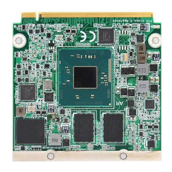
- Page 1 EmQ-i2301 Qseven® CPU Module User’s Manual Version 1.1 2017.05...
- Page 2 This page is intentionally left blank. - II -...
-
Page 3: Revision History
Revision History Version Release Time Description August, 2014 Initial release May, 2017 Add notes on USB ports in “1.3 Specifications” and remove SDIO related information. - i -... -
Page 4: Table Of Contents
Contents Contents Revision History .................i Contents .....................ii Preface....................iv Copyright Notice ..................iv Declaration of Conformity ..............iv CE ....................iv FCC Class A ..................v RoHS ....................v SVHC / REACH ................vi Warning ....................vi Replacing the Lithium Battery ..............vi Technical Support .................. -
Page 5: Contents
Contents 3.3. Security ..................28 3.4. Power ..................... 29 3.4.1 Advanced CPU Control ............30 3.4. Boot ....................32 3.5. Exit ....................34 - iii -... -
Page 6: Preface
Preface Preface Copyright Notice All Rights Reserved. The information in this document is subject to change without prior notice in order to improve the reliability, design and function. It does not represent a commitment on the part of the manufacturer. Under no circumstances will the manufacturer be liable for any direct, indirect, special, incidental, or consequential damages arising from the use or inability to use the product or documentation, even if advised of the possibility of such... -
Page 7: Fcc Class A
RoHS ARBOR Technology Corp. certifies that all components in its products are in compliance and conform to the European Union’s Restriction of Use of Haz- ardous Substances in Electrical and Electronic Equipment (RoHS) Directive 2002/95/EC. -
Page 8: Svhc / Reach
Preface SVHC / REACH To minimize the environmental impact and take more responsibility to the earth we live, Arbor hereby confirms all products comply with the restriction of SVHC (Substances of Very High Concern) in (EC) 1907/2006 (REACH --Registration, Evaluation, Authorization, and Restriction of Chemicals) regulated by the European Union. -
Page 9: Warranty
Preface Warranty This product is warranted to be in good working order for a period of two years from the date of purchase. Should this product fail to be in good working order at any time during this period, we will, at our option, replace or repair it at no additional charge except as set forth in the following terms. - Page 10 This page is intentionally left blank. - viii -...
-
Page 11: Chapter 1 Introduction
Chapter 1 Introduction Chapter 1 - Introduction - 1 -... -
Page 12: The Product
Introduction 1.1. The Product • Fanless Design • Soldered Onboard Intel® Atom™ Processor E3800 family • Intel® i210IT PCIe GbE controller • Dual Channels 24-bit LVDS, DDI Port • Extended Operating Temp.: -20 ~ 70ºC 1.2. About this Manual This manual is intended for experienced users and integrators with hardware knowledge of computers. -
Page 13: Specifications
Analog RGB signals (via Qseven® GF reserved pin) 1 x DDI port Expansion Bus 3 x PCIe x1 lanes, I2C Operating Temp. -20ºC ~ 70ºC (-4ºF ~ 158ºF) for EmQ-i2301 Watchdog Timer 1~ 255 levels Reset Dimension (L x W) 70 x 70 mm (2.76” x 2.76”) *Please don’t hot plug USB device with USB port0 to avoid that OS can’t... -
Page 14: Inside The Package
Before starting with the installation, make sure the following items are shipped. If any of the items is missing or appears damaged, contact your local dealer or distributor. 1 x EmQ-i2301 Qseven® CPU Module 1 x Driver CD 1 x Quick Installation Guide... -
Page 15: Ordering Information
Introduction 1.5. Ordering Information Intel Atom™ Processor E3825 Qseven CPU module with ® ® EmQ-i2301-E3825-2G 2GB memory soldered on module Intel Atom™ Processor E3845 Qseven CPU module with ® ® EmQ-i2301-E3845-2G 2GB memory soldered on module ® ® Intel Atom™ Processor E3825 Qseven... -
Page 16: Driver Installation Note
Introduction 1.6. Driver Installation Note The CPU board supports Windows 7 and Windows 8.1. Find the necessary drivers on the CD that comes with your purchase. For different OS, the driver/ utility installation may vary slightly, but generally they are similar. Find the drivers on CD by the following paths: Windows 8.1 Driver... - Page 17 Introduction Windows 7 Driver Path \Audio\32 bit Audio \Audio\64 bit \Chipset\32bit\Chipset Kit 57833 _32 Chipset \Chipset\64bit\Chipset Kit 57833 _64 \Ethernet\Intel\32bit\LAN 18.8.1 _32 Ethernet \Ethernet\Intel\64bit\LAN 18.8.1 _64 \Graphic\win32_153339 Graphics \Graphic\win64_153339 \GPIO I2C\windows 7 32_64\Intel_Atom_E3800_Processor_Win7_ GPIO/I2C IO_Drivers_MR1_v4_0 \TXE\TXE Kit 100885 USB3.0 \USB3.0\SetupUSB3 WINUSB \USB - 7 -...
- Page 18 This page is intentionally left blank. - 8 -...
-
Page 19: Chapter 2 Board Overview
Chapter 2 Board Overview Chapter 2 - Board Overview - 9 -... -
Page 20: Board Dimensions
Board Overview 2.1. Board Dimensions 70.00 52.00 36.58 35.94 22.86 18.00 3.00 67.00 Unit:mm - 10 -... -
Page 21: Block Diagram
Board Overview 2.2. Block Diagram DDR3L-1066/1333 MT/s Onboard DDR3L 2GB SDRAM 1 x eDP port Dual Channels 24-bit LVDS PTN3460 Analog R.G.B. (to Q7 RSV pin) 1 x DDI port (DDI1) 4 x USB 2.0 host ports(Support USB2.0 only) 4 x USB 2.0 Ports(Support USB1.1/2.0) 1 x HSIC SMSC Intel... -
Page 22: Connector Pin Definition
Board Overview 2.3. Connector Pin Definition Pin Signal Pin Signal Pin Signal Pin Signal HDA_SDI I2C_CLK GBE_MDI3- GBE_MDI2- HDA_SDO I2C_DAT GBE_MDI3+ GBE_MDI2+ THRM# WDTRIG# THRMTRIP# WDOUT (N/C) GBE_LINK100# GBE_LINK1000# GBE_MDI1- GBE_MDI0- USB_P7- USB_P6- GBE_MDI1+ GBE_MDI0+ USB_P7+ USB_P6+ GBE_LINK# GBE_ACT# USB_6_7_OC# USB_4_5_OC# GBE_CTREF SUS_S5#... -
Page 23: Board Overview
Board Overview Pin Signal Pin Signal Pin Signal Pin Signal DP1_TX3_P SDVO_INT+ (N/C) DP1_TX3_N SDVO_INT- (N/C) SPI_MOSI SPI_CS0# SPI_MISO SPI_CS1# (N/C) DP1_TX1_P DP1_AUX_C_P SPI_SCLK CRT_RED DP1_TX1_N DP1_AUX_C_N VCC_5V_SB VCC_5V_SB CRT_VSYNC CRT_GREEN DP1_TX2_P SDVO_TVCLKIN+ (N/C) CRT_HSYNC CRT_BLUE DP1_TX2_N SDVO_TVCLKIN- (N/C) DP1_TX0_P DP1_AUX_N DP1_TX0_N DP1_AUX_P... - Page 24 This page is intentionally left blank. - 14 -...
-
Page 25: Chapter 3 - Bios
Chapter 3 BIOS Chapter 3 - BIOS - 15 -... - Page 26 BIOS The BIOS Setup utility is featured by Insyde BIOS to configure the system settings stored in the system’s BIOS ROM. Insyde BIOS is activated once the computer powers on. After entering the utility, use the left/right arrow keys to navigate between the top menus and use the down arrow key to access one.
-
Page 27: Main
BIOS 3.1. Main The Main menu displays some BIOS info and features the settings of System Date and System Time. The BIOS info displayed is: Info Item Description BIOS Version Delivers the computer’s BIOS version. Project name Delivers the name of the project Delivers the date and time when the BIOS Setup utility was created/ Build Date and Time updated. -
Page 28: Advanced
BIOS 3.2. Advanced The Advanced menu controls the system’s CPU, IDE, Super IO, AHCI and USB. It also helps users monitor hardware health. - 18 -... - Page 29 BIOS The featured submenus are: Submenu Description Boot Configuration 3.2.1. Boot Configuration on page 20. PCI Express Configuration 3.2.2. PCI Express Configuration on page20. USB Configuration 3.2.3. USB Configuration on page 21. Audio Configuration 3.2.4. Audio Configuration on page 21. LPSS &...
-
Page 30: Boot Configuration
BIOS 3.2.1. Boot Configuration Setting Description Numlock Select Power-on state for Num lock 3.2.2. PCI Express Configuration Configures PCI Express by the following settings: Setting Description PCI Express Root Port Enables/disables this PCIe port. PCIe Speed Options are: Auto, Gen 1, Gen 2 Auto is the default. -
Page 31: Usb Configuration
BIOS 3.2.3. USB Configuration Select this submenu to view the status of the USB ports and configure USB features. The featured settings are: Setting Description XHCI Pre-Boot Mode Enables/Disables XHCI Pre-Boot mode support Support Set the mode of operation of xHCI controller xHCI Mode Options are Disabled/Enabled/Auto/Smart Auto(default) XCHI Controller... -
Page 32: Lpss & Scc Configuration
BIOS 3.2.5. LPSS & SCC Configuration The featured settings are: Setting Description LPSS & SCC Device Set the mode of LPSS & SCC Device Mode Options are ACPI mode(default)/PCI mode Set the mode of OS Selection OS Selection Options are Windows(default)/Android SCC eMMC Boot Set the mode of eMMC Boot mode Controller... -
Page 33: Miscellaneous Configuration
BIOS 3.2.6. Miscellaneous Configuration The featured settings are: Setting Description / Available Options HPET - HPET support Enables/Disables HPET support in Windows XP Set the state of System when power is re-applied after a Power State After G3 failure (G3 state) Options are S0 State(default)/S5 State Clock Spread Spectrum Enables/Disables Clock Spread Spectrum... -
Page 34: Video Configuration
BIOS 3.2.8. Video Configuration Configure video settings The featured setting is: 3.2.8.1 Video Configuration Setting Description Set Logo & SCU Resolution. Logo & SCU Resolution Options are Auto/640 x480/800 x 600/1024 x 768 3.2.8.2 VBT Hook Configuration Setting Description Set the option of CRT. Configure CRT as Options are Default / CRT / No Device CRT EDID Support... - Page 35 BIOS 3.2.8.5 IGD Configuration Setting Description Intergrated Graphics Enables/disables Intergrated Graphics Device. Device Set IGD or PCI graphic device as the Primary Display. Primary Display Options are Auto/IGD/PCie. RC6 (Render Standby) Enables/Disables Render standby support. PAVC Enables/disables Protected Audio Video control Power Managment Enables/disables Power mangement lock.
-
Page 36: Sata Configuration
BIOS 3.2.9. SATA Configuration Select this submenu to configure the SATA controller and HD. Setting Description Enables/disables the present SATA controller. SATA Controller(s) Enabled is the default. SATA Test Mode Enables/disables the SATA test mode. Configures how to sun the SATA drives. Configures SATA Mode Options available are AHCI (default) and IDE. -
Page 37: Lm90 Thermal Sensor
BIOS 3.2.11. LM90 Thermal Sensor 3.2.12. SIO FINTEK81866 Configures SIO by the following settings: Setting Description Set the state of Power Loss mode Power Loss mode Options are Always On(default)/Always Off Serial Port Enables/disables the Serial port. Serial Port Base I/O Address A/B/C/D Setup the Base I/O Address of the Serial Port. -
Page 38: Security
BIOS 3.3. Security The Security menu sets up the password for the system’s administrator account. Once the administrator password is set up, this BIOS Setup utility is limited to access and will ask for the password each time any access is attempted. The featured setting is: Setting Description... -
Page 39: Power
BIOS 3.4. Power The Power menu sets up the power option of system The featured setting is: Setting Description Advanced 3.4.1 Advanced CPU Control on page CPU Control Enables or diables Wake on PME. Wake on PME Determines the action taken when the system power is off and a PCI Power Management Enable wake up event occurs. -
Page 40: Advanced Cpu Control
BIOS 3.4.1 Advanced CPU Control Setting Description Use XD Enables or disables processor XD capability. Capability Sets whether the processor should limit the maximum CPUID input value to 03h when the operating system queries it upon startup. Limit CPUID Select Enabled to allow a processor with Intel® Hyper- Max value Threading technology to work with an operating system that doesn’t support it. - Page 41 BIOS P-States(IST) Enables/disables processor performance states (P-States) Boot Select the performance state that BIOS will set before OS handoff Performance Mode Enables/disables processor Turbo mode (EMTTM enabled is Turbo Mode required) C-States Enables/disables processor idle power saving states (C-states) Enhanced Enables/disables P-state transitions to occur in combination with C-States C-states.
-
Page 42: Boot
BIOS 3.4. Boot The Boot menu configures how to boot up the system such as the configuration of boot device priority. The featured settings are: Setting Description Allow InsydeH20 to Skip certain tests while booting . Quick Boot This will descrese the time need to boot the system. Quiet Boot Disables or enables booting in text mode. - Page 43 BIOS USB Boot Disables or enables booting to USB boot devices. Set the waiting seconds before booting the default boot Timeout selection Automatic Failover Enables/disables the Automatic Failover. - 33 -...
-
Page 44: Exit
BIOS 3.5. Exit The Save & Exit menu features a handful of commands to launch actions from the BIOS Setup utility regarding saving changes, quitting the utility and recovering defaults. The features settings are: Setting Description Exit Saving Changes Saves the changes and quits the BIOS Setup utility. Save Changes Without Exit Save Changes but does not quit the BIOS.
Need help?
Do you have a question about the EmQ-i2301 and is the answer not in the manual?
Questions and answers