Table of Contents
Advertisement
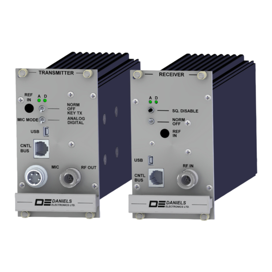
MT-4E vhf & Uhf
rEcEivEr & TransMiTTEr
insTrUcTion ManUal
136–174 MHz / 380–406 MHz / 406–470 MHz /
470–520 MHz / 768–869 MHz / 896–960 MHz
Covers Models:
VR-4E150-00-000
VR-4E150-A0-000
UR-4E380-00-000
UR-4E420-00-000
UR-4E420-A0-000
UR-4E440-00-000
UR-4E460-00-000
UR-4E460-A0-000
UR-4E500-00-000
© 2007–2011 Daniels Electronics Ltd. All rights reserved. No part
of this publication may be reproduced, stored in a retrieval system
or transmitted in any form or by any means, electronic, mechanical,
photocopying, recording or otherwise, without the prior written consent
of Daniels Electronics Ltd.
The stylized "Daniels Electronics Ltd." and "DE" logo are registered
Canadian and US trademarks of Daniels Electronics Ltd.
The stylized "Daniels Electronics Ltd." and "DE" logo are trademarks of
Daniels Electronics Ltd.
Document Number:
IM08-MT-4E-TXRX
Revision:
P1162
Revision Date:
Jun 2011
UR-4E768-00-000
UR-4E800-00-000
UR-4E850-00-000
VT-4E150-00-800
UT-4E380-00-600
UT-4E450-00-800
UT-4E500-00-800
UT-4E850-00-300
UT-4E900-00-300
Daniels Electronics Ltd.
Victoria, BC
PRINTED IN CANADA
Advertisement
Table of Contents
Troubleshooting

Summary of Contents for Daniels VR-4E150-00-000
-
Page 1: Instruction Manual
Daniels Electronics Ltd. The stylized “Daniels Electronics Ltd.” and “DE” logo are registered Canadian and US trademarks of Daniels Electronics Ltd. The stylized “Daniels Electronics Ltd.” and “DE” logo are trademarks of Daniels Electronics Ltd. Document Number: IM08-MT-4E-TXRX Daniels Electronics Ltd. - Page 2 DOCUMENT CONTROL This document has been produced, verified and controlled in accordance with Daniels Electronics’ Quality Management System requirements. Please report any errors or problems to Daniels Electronics’ Customer Service Department. DOCUMENT REVISION Daniels Electronics Ltd. utilizes a three-level revision system. This DEFINITION system enables Daniels to identify the significance of a revision.
- Page 3 FCC/IC MPE limits. This exclusion is subject to the limits specified in FCC 47 CFR 1.1307 (b), 1.1310 and IC RSS-102 Issue 2 Sect 4. Daniels Electronics Ltd. has no reason to believe that this excluded transmitter encompasses exceptional characteristics that could cause non-compliance.
- Page 4 This Page Intentionally Left Blank MT-4E VHF & UHF Receiver & Transmitter Instruction Manual IM08-MT-4E-TXRX-P1162...
-
Page 5: Table Of Contents
Contents General Information ............... Introduction ....................Channel and Bank Selection ..............Radio Service Software Programming ........Introduction ....................Radio System Configurations ..........Repeater ....................Analog Fixed (Base) Station Interface ............Digital Fixed (Base) Station Interface ............VHF & UHF Receivers and Transmitters ....... VHF &... - Page 6 Contents (continued) 700 / 800 / 900 MHz Parts List ..........700 / 800 MHz Receiver Electrical Parts ..........700 / 800 MHz Receiver Mechanical Parts ..........700 / 800 MHz Receiver P25 Digital Firmware ........700 / 800 / 900 MHz Receiver and Transmitter Encryption ..... 700 / 800 / 900 MHz Receiver and Transmitter RSS .......
-
Page 7: General Information
SARSAT. hardware adjustments required. The MT-4E series is compatible with all Daniels’ subrack and base station enclosures. It supports a basic analog interface and may be used in a mixed system with MT-3 and MT-4 series receivers and transmitters. -
Page 8: Vr-4E150-A0
Motorola KVL 3000 Plus Keyloader in conjunction with a Daniels Keyloader Cable. The Daniels Keyloader Cable plugs into the front panel RJ45 jack on the front of the receiver or transmitter module. -
Page 9: Channel And Bank Selection
General Information C H a n n E l an d B an k SEl EC tI on Four channel select lines, CSEL 0 – CSEL 3, from the motherboard are brought into the receiver and transmitter modules by the 48-pin rear connector, allowing selection of 16 different channels. These signals are normally pulled low in the receiver and transmitter, but are typically set by jumpers on the motherboard to select Channel 1 by default. - Page 10 This Page Intentionally Left Blank MT-4E VHF & UHF Receiver & Transmitter Instruction Manual IM08-MT-4E-TXRX-P1162...
-
Page 11: Radio Service Software Programming
For current RSS versions and instructions, refer to up-to-date help files on the Daniels Electronics website (www.danelec.com > Products > Software > Radio Service Software (RSS) > RSS Download Page). Once RSS is downloaded with either the full or demo version, click Help to access the help files. - Page 12 Radio Service Software Programming Installation The RSS should install automatically once the CD is inserted. If not, run SETUP.EXE, located on the CD. NOTE: The receiver and transmitter must be programmed separately. Once the connections are made, the RSS may be run on the computer and the radio switched on. The first time a receiver or transmitter is connected, the USB drivers will need to be installed from the CD using the Hardware Update Wizard.
-
Page 13: Radio System Configurations
RadIo SyStEM ConFIGuRatIonS R E P E at ER The MT-4E series receivers and transmitters may be configured in a repeater configuration. The standard way of setting up a repeater system is to connect the receiver to the transmitter through a Radio Interconnect Cable plugged into the RJ45 CNTL BUS connectors on the front panels of each radio module. -
Page 14: Analog Fixed (Base) Station Interface
Radio System Configurations an a l o G FI xE d ( B aS E) Stat Ion In t E R Fa C E The MT-4E series receivers and transmitters may be configured in a fixed (or base) station configuration with an analog interface. An Audio Control Card or Base Controller is added to the system for E&M control. -
Page 15: Vhf & Uhf Receivers And Transmitters
vHF & uHF RECEIvERS and tRanSMIttERS The following section provides information that is primarily for VHF / UHF receiver and transmitter modules. For specific information on 700 / 800 / 900 MHz receiver and transmitter modules, see the 700 / 800 / 900 MHz section in this manual. MT-4E VHF &... - Page 16 This Page Intentionally Left Blank MT-4E VHF & UHF Receiver & Transmitter Instruction Manual IM08-MT-4E-TXRX-P1162...
-
Page 17: Vhf & Uhf Hardware Tuning And Troubleshooting
vHF & uHF HaRdWaRE tunInG and tRouBlESHootInG R EPa IR n o tE MT-4E Receivers and Transmitters employ a high percentage of surface mount components which should not be removed or replaced using an ordinary soldering iron. Removal and replacement of surface mount components should be performed only with specifically designed surface mount rework and repair stations complete with... -
Page 18: Recommended Test Equipment
Communications Service Monitor (P25 Digital and Analog) IFR 2975 Alignment Tools Daniels A-TK-04 It is recommended that the radio communications test set be frequency-locked to an external reference (WWVH, GPS, Loran C) so that the high-stability local oscillator may be accurately set. -
Page 19: Receiver Jumpers
VHF & UHF Hardware Tuning and Troubleshooting R E C E Iv E R J u M PE R S vHF / uHF Receiver Mainboard PCB 50164 Jumper Default Position Function / Description When installed enables Clear Keys 1 Input When installed enables Clear Keys 2 Input When installed enables power to Discriminator Output amplifier RX Mode Pullup... -
Page 20: Transmitter Jumpers
VHF & UHF Hardware Tuning and Troubleshooting tR a n S M IttE R J u M PE R S vHF / uHF transmitter Mainboard PCB 50156 Jumper Default Position Function / Description X: A/D Front Panel Switch selects transmitter A/D mode Y: A/D External Input selects transmitter A/D mode X: MIC OUT connects to Microphone Audio Input Y: MIC IN connects to Microphone Audio input... -
Page 21: Receiver Troubleshooting
If the RSS returns “Device Not Responding,” physically inspect the USB cable and connection, check the Daniels USB driver and check that the USB is recognized by the Device Manager. If the RSS still does not recognize the connection, the most likely fault is on the UDB. - Page 22 VHF & UHF Hardware Tuning and Troubleshooting Receiver Mainboard Check the following test points on the receiver mainboard: Test Point Signal Monitored Typical Voltage Voltage from motherboard +13.8 VDC line +13.8 VDC** Regulated +9.5 VDC from motherboard +9.5 VDC ± 5 % Switched +13.8 VDC line from front panel switch +13.8 VDC** TP37...
- Page 23 VHF & UHF Hardware Tuning and Troubleshooting Synthesizer and udB Module The Synthesizer Module and UDB are bound together through their communication link. At this level of fault diagnosis it is not feasible to isolate the problem between the two units. If the receiver front panel ON/OFF switch is set from the OFF position to the NORM position and the two front panel LEDs stay on, check that the synthesizer and the UDB are properly seated on the receiver mainboard and check the following test points on the UDB.
-
Page 24: Transmitter Troubleshooting
If the RSS returns “Device Not Responding,” physically inspect the USB cable and connection, check the Daniels USB driver and check the connection through the Device Manager. If the RSS still does not recognize the connection, the most likely fault is on the UDB. - Page 25 VHF & UHF Hardware Tuning and Troubleshooting transmitter Mainboard Check the following test points on the transmitter mainboard: Test Point Signal Monitored Typical Voltage Voltage from Motherboard +13.8 VDC Line +13.8 VDC** Regulated +9.5 VDC from Motherboard +9.5 VDC ± 5 % USB Connector Power +3.0 VDC or +5.0 VDC Switched +13.8 VDC Line from Front Panel Switch...
-
Page 26: System Troubleshooting
VHF & UHF Hardware Tuning and Troubleshooting Transmitter Amplifier Set the front panel switch on the transmitter to KEY TX and check that the transmitter output power is approximately 0.5 to 8.0 W for VHF and UHF models. Check the following pins on Connector J1 (while the transmitter is keyed): Signal Monitored Typical Voltage RF Enable / Power Control (+0.5 to +3.0 VDC... -
Page 27: 48-Pin Motherboard Interface Connector
VHF & UHF Hardware Tuning and Troubleshooting 48 -P I n Mo t H E R Boa R d In tER Fa C E C on n E C toR A 48-pin connector is used for interfacing the MT-4E Motherboard to the receiver and transmitter. Receiver Pin Name Pin Name... - Page 28 This Page Intentionally Left Blank MT-4E VHF & UHF Receiver & Transmitter Instruction Manual IM08-MT-4E-TXRX-P1162...
-
Page 29: Vhf And Uhf Parts List
vHF and uHF PaRtS lISt v H F / u H F R EC EIv ER El EC tR I C al Pa Rt S l IS t Part Number Description Product A11-RX4E-MAIN-01 RX MB,MT-4E 100-400MH INCL UDB UHF and VHF A11-UDB UNIVERSAL DAUGHTER BOARD A11-FE4-150... -
Page 30: Vhf / Uhf Receiver Mechanical Parts List
VHF and UHF Parts List vH F / u H F R EC E Iv ER ME C H an IC al PaRt S l IS t Part Number Description Product 3702-62501010 CASE, 14HP RF PLUG-IN, MT-3 RX 3702-10000120 FASTENER, QUICK RELEASE, GRAY 5630-12023250 GASKET, BeCu,3FINGER,.71",CLIP 3702-10000614... -
Page 31: Vhf / Uhf Transmitter Electrical Parts List
VHF and UHF Parts List v H F / u H F t R an S M It t ER El E C t R IC a l PaRtS l I St Part Number Description Product A21-TX4E-MAIN-01 TX, MB ASSY, MT-4E, INCL UDB A11-UDB UNIVERSAL DAUGHTER BOARD A21-VPA155-08... - Page 32 This Page Intentionally Left Blank MT-4E VHF & UHF Receiver & Transmitter Instruction Manual IM08-MT-4E-TXRX-P1162...
-
Page 33: 700 / 800 / 900 Mhz Receivers And Transmitters
7 0 0 / 8 0 0 / 9 0 0 M H z RE C E I v E RS a n d t Ra n SM It tE RS The following section provides information that is primarily for 700 / 800 / 900 MHz receiver and transmitter modules. - Page 34 This Page Intentionally Left Blank MT-4E VHF & UHF Receiver & Transmitter Instruction Manual IM08-MT-4E-TXRX-P1162...
-
Page 35: 700 / 800 / 900 Mhz Jumpers
700 / 800 / 900 MHz JuMPERS R E C E Iv E R J u M PE R S 700 / 800 MHz Receiver Mainboard PCB 50171 Jumper Default Position Function / Description Enable Clear Keys 1 Enable Clear Keys 2 Enable Power to Discriminator Circuit Enable Pullup Resistor on RX_Mode Bypass 330 nF Audio Cap... -
Page 36: Transmitter Jumpers
700 / 800 / 900 MHz Jumpers 700 / 800 MHz Receiver Mainboard Jumpers (continued) JU23 Jumper for D&D Testing (Disconnect SSI Data Line) JU24 Jumper for D&D Testing (Disconnect SSI Data Line) JU25 Jumper for D&D Testing (Disconnect SSI Data Line) JU26 Jumper for D&D Testing (Disconnect SPI Data Line) JU27... -
Page 37: 700 / 800 / 900 Mhz Parts List
700 / 800 / 900 MHz PaRtS lISt 70 0 / 8 0 0 MH z R E C EIvER El E C tR I C al PaRt S Part Number Description A14-RX4E-MAIN-01 RX,MB,MT-4E 700-900MH INCL UDB A11-UDB UNIVERSAL DAUGHTER BOARD A14-FE4-770 PRESELECTOR/4E,CLASS B,768-776 A15-FE4-800... -
Page 38: 700 / 800 Mhz Receiver P25 Digital Firmware
700 / 800 / 900 MHz Parts List 700 / 800 MHz Receiver Mechanical Parts (continued) Part Number Description 5812-2M5PP06S SCREW, M2.5 X 6, PAN/PHIL., A2 5812-2M5VP08S SCREW, M2.5x8,OVAL C/S/PHIL,A2 5812-3M0PP08T SCREW, M3 x 8, PAN/PHIL, BLACK 5812-3M0VP08S SCREW, M3 x 8,OVAL C/S/PHIL,A2 5917-7B4BM30T STANDOFF, 7/32OD,1/4L,M3,SWAGE 5927-5SFBM25T... -
Page 39: 700 / 800 / 900 Mhz Transmitter Mechanical Parts
700 / 800 / 900 MHz Parts List 70 0 / 8 0 0 / 9 0 0 M H z t R an SM I tt E R M EC H an I C al PaRt S Part Number Description A89-MIC4-08 CABLE/CONN ASSY,MICROPHONE CON... - Page 40 This Page Intentionally Left Blank MT-4E VHF & UHF Receiver & Transmitter Instruction Manual IM08-MT-4E-TXRX-P1162...
-
Page 41: Specification Data Sheets
SPECIFICatIon data SHEEtS This section contains detailed specifications for RF modules within the scope of this manual. To verify performance and set-up test procedures, please refer to these data sheets when performing technical operations on the equipment. MT-4E VHF & UHF Receiver & Transmitter Instruction Manual IM08-MT-4E-TXRX-P1162... - Page 42 This Page Intentionally Left Blank MT-4E VHF & UHF Receiver & Transmitter Instruction Manual IM08-MT-4E-TXRX-P1162...
-
Page 43: Vhf And Uhf Receiver Performance Specifications
Specification Data Sheets v HF a n d u H F R E C EI vE R P E R FoR M a n C E S PE C IF IC atI on S NOTE: 380–406 MHz and 430–450 MHz Receiver specifications are not included in these VHF / UHF receiver specifications;... - Page 44 Specification Data Sheets VHF and UHF Receiver Performance Specifications (continued) Audio Output: 600 Ω balanced line output (configurable for unbalanced line); De-emphasis or Flat output, +3 dBm maximum level Audio Distortion: Analog: ≤ 2.0% (25°C); ≤ 3.0% (-30˚C to +60˚C) Digital as per TIA / EIA 102.CAAB* Front Panel Controls: Receiver Power On (Norm) / Off...
-
Page 45: 380-406 Mhz Receiver Performance Specifications
Specification Data Sheets 38 0– 406 MH z R EC E Iv ER P E R FoR M a n C E S PE C IF IC atI on S General Frequency Range: 380–406 MHz Channel Spacing: 12.5, 15, 25 and 30 kHz Channel Selection: 6.25 kHz Number of Channels:... - Page 46 This Page Intentionally Left Blank MT-4E VHF & UHF Receiver & Transmitter Instruction Manual IM08-MT-4E-TXRX-P1162...
-
Page 47: 430-450 Mhz Receiver Performance Specifications
Specification Data Sheets 43 0– 450 MH z R EC E Iv ER P E R FoR M a n C E S PE C IF IC atI on S General Frequency Range: 430–450 MHz Channel Spacing: 12.5, 15, 25 and 30 kHz Channel Selection: 6.25 kHz Number of Channels:... - Page 48 This Page Intentionally Left Blank MT-4E VHF & UHF Receiver & Transmitter Instruction Manual IM08-MT-4E-TXRX-P1162...
-
Page 49: Vhf And Uhf Transmitter Performance Specifications
Specification Data Sheets v HF a n d u H F tR an S M It t E R P E R FoR M a n C E S PE C IF IC atI on S NOTE: 380–406 MHz Transmitter specifications are not included in these VHF / UHF transmitter specifications;... -
Page 50: Vhf And Uhf Physical Specifications
• Gold-plated module connectors Module Design: • Compact Eurostandard modular design • Plug-in modules mate with the Daniels standard MT-4E repeater subrack • Subracks / modules comply with IEEE 1101, DIN 41494 and IEC 297-3 (mechanical size / modular arrangement) External Connections: RF Connection: Type-N connector located on the module front panel. -
Page 51: 380-406 Mhz Transmitter Performance Specifications
Specification Data Sheets 38 0– 406 MH z tR an S M It tE R P E R FoR M a n C E S PE C IF IC atI on S General Frequency Range: 380–406 MHz Carrier Frequency Stability: ±... -
Page 52: 380-406 And 430-450 Mhz Physical Specifications
• Gold-plated module connectors Module Design: • Compact Eurostandard modular design • Plug-in modules mate with the Daniels standard MT-4E repeater subrack • Subracks / modules comply with IEEE 1101, DIN 41494 and IEC 297-3 (mechanical size / modular arrangement) External Connections: RF Connection: Type-N connector located on the module front panel. -
Page 53: 700 / 800 Mhz Receiver Performance Specifications
Specification Data Sheets 70 0 / 8 0 0 MH z R E C EIvER P E R FoR M a n C E S PE C IF IC atI on S General Frequency Range: 768–776 MHz, 798–824 MHz, 851–869 MHz Channel Spacing: 12.5 and 25 kHz Channel Selection:... - Page 54 Specification Data Sheets 700 / 800 MHz Receiver Performance Specifications (continued) DCS Decode: Programmable to any of 83 DCS sequences. Normal or inverted DCS can be selected. IC Certification No.: 142A-UR4E768 142A-UR4E800 142A-UR4E850 FCC ID: n/a – Declaration of Conformity (DOC) * P25 Digital specifications are applicable only for modules with the P25 Digital firmware upgrade.
-
Page 55: 700 / 800 / 900 Mhz Transmitter Performance Specifications
Specification Data Sheets 70 0 / 800 / 9 0 0 M H z tR a nS M It tE R P E R FoR M a n C E S PE C IF IC atI on S General Frequency Range: 768–869 MHz, 896–960 MHz Carrier Frequency Stability: ±... -
Page 56: 700 / 800 / 900 Mhz Physical Specifications
• Gold-plated module connectors Module Design: • Compact Eurostandard modular design • Plug-in modules mate with the Daniels standard MT-4E repeater subrack • Subracks / modules comply with IEEE 1101, DIN 41494 and IEC 297-3 (mechanical size / modular arrangement) External Connections: RF Connection: Type-N connector located on the module front panel. -
Page 57: Glossary Of Terms
GloSSaRy oF tERMS Bandwidth The difference between the limiting Digital Coded Squelch. frequencies of a continuous frequency band. Typically measured in kilohertz. May be Digital Signal Processor – a specialized considered the amount in kilohertz required microprocessor. for a single communications channel. DTMF Dual-Tone Multi-Frequency –... - Page 58 Glossary of Terms Modulation Trunked (System) A controlled variation of any property of a Systems with full-feature sets in which carrier wave for the purpose of transferring all aspects of radio operation—including information. RF channel selection and access—are centrally managed. Most Significant BIT.
Need help?
Do you have a question about the VR-4E150-00-000 and is the answer not in the manual?
Questions and answers