Table of Contents
Advertisement
Quick Links
VNS2210 Amplifier & Controller Installation Guide
VNS2210 Amplifier & Controller Installation
1.
Determine the installation location for the VNS2210 device. Consider the following when determining the installation location:
Standard VNS2210 device is equipped with AC to DC power adaptor and requires a standard 110VAC or 220VAC power
outlet. The power adaptor consists of 6' DC power cable and 6' of AC power cord. Consider these cable lengths and the
distance between the power outlet and the VNS2210 device.
For VNS2210 devices equipped with VNS2256 option: The solar panel is equipped with 15' feet of power cable. Consider
this cable length and the distance between the outdoor solar panel installation location and the VNS2210 device.
For VNS2210 devices equipped with VNS2267, VNS2268, VNS2261 or VNS2263 option: The intercom wall station is
equipped with 25' feet of data cable. Consider this cable length and the distance between the intercom wall station
installation location and the VNS2210 device.
For VNS2210 devices equipped with VNS2264 option: The ambient noise level sensor is equipped with 10' feet of data
cable. Consider this cable length and the distance between the ambient noise level sensor installation location and the
VNS2210 device.
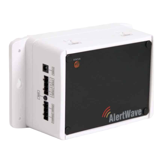
2.
Position the VNS2210 device on the mounting surface and confirm that it is vertical to the floor.
Note: When the device is installed properly, the LED should be on the left top corner (front view).
3.
Secure the VNS2210 device to the wall using screws appropriate for the mounting surface (use 1.5"-2" long screws).
4.
If an external antenna (2.5db or 3db gain) is used, install it on the BNC connector.
5.
Connect the output devices to their respective port. Below are the available connector types that are installed on your device:
Strobe Lights: Strobe Light or 12VDC Controlled Device (for VNS2282 option, STROBE 1 and STROBE 2 ports)
Speakers: Speaker Audio Output (for VNS2281 option, SPEAKER 1 and SPEAKER 2 ports)
Intercom: Intercom Wall Station or Ambient Noise Level Control (for VNS2267, VNS2268, VNS2261, VNS2263 & VNS2264
options, INTERCOM port)
Audio: Line Level Audio Output with Dry-Contact Closure (for VNS2284 option, AUDIO and RELAY ports)
Relay: Dry-Contact Closure (for VNS2285 option, RELAY ports)
6.
Connect the other end of each cable to the appropriate output device and verify proper connections.
7.
Connect the power adaptor male connector to the POWER port of the VNS2210 device.
Note: The VNS2210 devices should be protected from direct rain and snow, and if possible, from direct sun. Outdoor installation
should include an overhang to protect the VNS2210 device from direct rain, snow and sun.
VNS2267 & VNS2268 - Two Way Intercom Option
1.
Before installation, consider the distance between the VNS2210 device and the VNS2267 or VNS2268 intercom wall station. The
VNS2210 device and the intercom wall station will be connected using the provided CAT5 cable (25' long).
2.
Follow steps 1-7 of the VNS2210 Amplifier & Controller Installation described above.
3.
Disconnect the power source connector from the POWER port of the VNS2210 device.
4.
Run the data cable between the VNS2210 device and the intercom wall station.
5.
Connect the RJ45 data cable to the intercom wall station (Image 3).
6.
Attach the intercom wall station to a single gang box using supplied 2 machine screws. For surface installation, use the
metal/wood screws (Image 2).
Note: When mounting directly to wall surface (without gang box), remove the breakable data cable outlet (Image 3) and pass
the cable through the opening at the bottom.
7.
Connect the other end of the cable (RJ45 connector) to the INTERCOM port on the VNS2210.
8.
Connect the power source connector to the POWER port of the VNS2210 device.
9.
Document the location and the serial number of the main VNS2210 device.
Note: The serial number of the VNS2210 device is required for system programming.
10. To test communication with the base station, push the CALL button on the wall station.
VNS2210 Amplifier & Controller Installation Guide – Version 2.00
Advertisement
Table of Contents

Subscribe to Our Youtube Channel
Summary of Contents for visiplex VNS2210
- Page 1 Determine the installation location for the VNS2210 device. Consider the following when determining the installation location: Standard VNS2210 device is equipped with AC to DC power adaptor and requires a standard 110VAC or 220VAC power outlet. The power adaptor consists of 6’ DC power cable and 6’ of AC power cord. Consider these cable lengths and the distance between the power outlet and the VNS2210 device.
- Page 2 For VPS (note: VPS software does not support all versions and models): 7.1 VPS will be connected to the receiver module once it is open. Connected to VNS2210 should be displayed in the lower right hand corner of the screen.
- Page 3 Adjust the solar panel to an angle between 45 and 60 degree from the horizon. Tighten all screws to lock mounting bracket and solar panel in position. Connect the solar panel male connector to the POWER port of the VNS2210 device. Allow 24 hours for battery to recharge.
- Page 4 Follow these steps to program a weekly schedule (see IMPORTANT NOTES at the end of this section): 1. Download and install the VPS software and USB driver. Make sure the VNS2210 is powered on and connected to the USB port on the PC.
- Page 5 6. Use the Upload command to program a schedule that was loaded using the Open command. 7. It is recommended that each schedule used will be downloaded from the VNS2210 and saved to the disk with a name that will describe it appropriately.
- Page 6 General description for the updated event. Description Note: This field is saved on the PC database only and is not programmed in to the VNS2210. Type of tone or alert that will be activated by the VNS2210. Alert 11 and up will activate a customized user-programmed audio alert stored in the Alert Type VNS2210.
- Page 7 VNS2210 after schedule changes are completed. 4. The execution of the schedule programmed in to the VNS2210 is dependent on the date and time stored in its internal clock. This internal clock has to be kept accurate by receiving time updates from a PC connected to it via the USB port.
- Page 8 This equipment generates, uses, and can radiate radio frequency energy and, if not installed and used in accordance with the instructions, may cause harmful interference to radio communications. However, there is no guarantee that interference will not occur in a particular installation. If this equipment does cause harmful interference to radio or television reception, which can be determined by turning the equipment off and on, the user is encouraged to try and correct the interference by one or more of the following measures: ‐Reorient or relocate the receiving antenna. ‐Increase the separation between the equipment and the receiver. ‐Connect the equipment into an outlet on a circuit different from that to which the receiver is connected. ‐Consult the dealer or an experienced radio/TV technician for help. RF Radiation Hazard Warning (products with activated transmit option only): To ensure compliance with FCC RF exposure requirements, this product should be positioned no less than 30 cm from your body or nearby persons during continuous use. VNS2210 Amplifier & Controller Installation Guide – Version 2.00...
Need help?
Do you have a question about the VNS2210 and is the answer not in the manual?
Questions and answers