
Related Manuals for NetBurner SB72

Summary of Contents for NetBurner SB72
- Page 1 B u r n e r SB72 User's Manual Revision 1.6 November 13, 2007 SB72 User's Manual, 350030-006...
-
Page 2: Table Of Contents
Device Connection Settings........................8 Serial Data Port Settings........................9 Connector Descriptions....................10 Specifications ........................12 RS-232 NULL Modem Wiring..................12 Network IP Address Configuration................. 13 Web Browsers and Proxy Servers..................13 Testing with a Telnet Connection..................14 SB72 User's Manual, 350030-006 Page 2... -
Page 3: Overview
The SB72 comes preprogrammed and ready to run on your network. Before you can begin using the device, some basic configuration is required to tell the SB72 what type of serial interface you want to use, the network address you want the SB72 to respond to, the serial data baud rate, and the TCP/IP listening port number. - Page 4 Key: X = don’t care, Open = No connection, Closed = Jumper pins Note for RS-232 Operation: The SB72 can run 2 channels without hardware handshaking. If RTS and CTS are required, then only Port 1 can be used. RTS and CTS are available at TTL levels on the J5 connector for both channels.
-
Page 5: Hardware Configuration Examples
Optional: Install Jumpers JP4 and JP5 on pins 2-3 for RTS/CTS handshaking • RS-485 Remove all jumpers • Install Jumper JP2 • Install Jumper JP1 on pins 1-2 (full duplex) or 2-3 (half duplex) • SB72 User's Manual, 350030-006 Page 5... -
Page 6: Network Configuration
Run IPSetup.exe. You will see a dialog box like the one below: Select the "Find" button and locate the SB72 in the list box. If your SB72 does not appear in the list box, verify the power and link LED's are illuminated; if not, correct any cabling errors. Note that IPSetup uses a UDP broadcast protocol similar to BOOTP and will not operate through a router. -
Page 7: Operational Configuration
Once the network parameters have been configured you can use the web server interface to modify setting of the SB72. To access the web page on the SB72, open a web browser and enter the numeric IP Address in the address field. -
Page 8: Device Connection Settings
TCP server will disconnect the current TCP/IP connection and allow the new incoming connection request to connect. Outgoing Connections If this option is enabled, the SB72 will initiate a connection to an outside destination when the selected conditions are met. Options are: Don't Initiate Connections •... -
Page 9: Serial Data Port Settings
Data Bits Select number of data bits Data Parity Select none, odd or even parity Data Stop Bits Select 1 or 2 stop bits Flow Control Selects serial port flow control: none, Xon/Xoff, or RTS/CTS SB72 User's Manual, 350030-006 Page 9... -
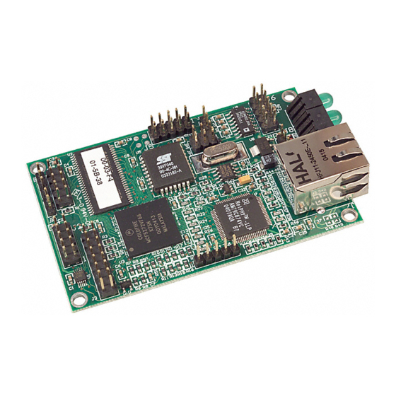
Page 10: Connector Descriptions
J5 – Serial TTL Dual Row 10-Pin Header This connector allows access to TTL level serial ports 0 and 1. Note that pin 9 is a VCC 5V input, which allows for a single connector interface with TTL serial and power to the SB72. Signal... - Page 11 J7 – RJ-45 Ethernet Connector Signal Signal J8 – Power Connector Single row straight 3-pin header. PCB REVISION 1.3 AND HIGHER Signal LEDS LED1: Ethernet speed, 10 or 100 LED2: Link Light LED3: Power SB72 User's Manual, 350030-006 Page 11...
-
Page 12: Specifications
The following table and diagram show how to create a null modem cable/adapter for RS-232 connections. A null modem cable will be required if you are connecting the SB72 to a PC using the standard NetBurner 10-pin header to DB9 ribbon cable connector. -
Page 13: Network Ip Address Configuration
Card, don't change your Dial-Up Adapter settings) Set the IP address of the NetBurner board to 10.1.1.11 • Set the network mask for both the PC network adapter and the NetBurner board to 255.255.255.0 • Web Browsers and Proxy Servers If you are working on a corporate LAN that uses a proxy server for Internet web browsing, you will need to exclude the IP address of the NetBurner hardware in your web browser’s proxy server settings/preferences. -
Page 14: Testing With A Telnet Connection
For a serial terminal you can use Hyper Terminal, or download MTTTY from the NetBurner web site. In the following examples an IP Address of 10.1.1.2 will be used for the SB72. Replace this number with your specific IP Address you assigned during configuration. - Page 15 Mouser Electronics Authorized Distributor Click to View Pricing, Inventory, Delivery & Lifecycle Information: NetBurner SB72-301CR...
Need help?
Do you have a question about the SB72 and is the answer not in the manual?
Questions and answers