Table of Contents
Advertisement
Quick Links
Thank you very much for purchasing this product.
To ensure correct and safe usage with a full understanding of this product's performance, please be sure to read
through this manual completely and store it in a safe location.
Unauthorized copying or transferral, in whole or in part, of this manual is prohibited.
The specifications of this product and the contents of this manual are subject to change without notice.
This manual and the product have been prepared and tested as much as possible. If you find any misprints or
errors, please inform Roland DG Corp.
Roland DG Corp. assumes no responsibility for any direct or indirect loss or damage that may occur through use
of this product, regardless of any failure to perform on the part of this product.
Roland DG Corp. assumes no responsibility for any direct or indirect loss or damage that may occur with respect
to any article made using this product.
USER'S MANUAL
Advertisement
Table of Contents

Summary of Contents for Rolando Texart XT-640
- Page 1 USER'S MANUAL Thank you very much for purchasing this product. To ensure correct and safe usage with a full understanding of this product's performance, please be sure to read through this manual completely and store it in a safe location. ...
- Page 2 This product is equipped with an "eT-Kernel Multi-Core Edition" eT-Kernel and a "PrConnect(R)/Pro" TCP/IP pro- tocol stack, both made by eSOL Co., Ltd. eT-kernel and PrConnect are registered trademarks of eSOL Co., Ltd. Roland DG Corp. has licensed the MMP technology from the TPL Group.
-
Page 3: Table Of Contents
Contents Contents ........................1 Chapter 1 Machine Highlights ..................5 Part Names and Functions ..................6 Printer Unit ................................6 Operation Panel ..............................8 Warning Labels ..............................9 Vignettes d'avertissement ........................10 Menu List ........................11 Main Menu ................................11 Language and Unit Menu ..........................14 Cleaning Menu ..............................14 Dryer Settings Menu ............................15 Important Notes on Handling and Use ..............16 Chapter 2 Basic Operation ....................17... - Page 4 Contents Maintenance That Should Be Performed Daily ............63 Disposing of Discharged Fluid ........................63 Cleaning ................................65 Care and Maintenance of the Print Heads ....................66 When Normal Cleaning Is Not Effective ..............67 Medium Cleaning ..............................67 Powerful Cleaning .............................68 If Colors Are Uneven ....................69 Mixing the Ink by Shaking the Ink Pouch ....................69 Light Choke Cleaning ............................69 Maintenance That Should Be Performed More than Once a Month ......71...
- Page 5 Contents Preventing Soiling of the Media and Dot Drop-Out ................112 Using Sticky Media ............................113 Printing with Crop Marks ..................114 Printing with Crop Marks ..........................114 Using the Media Take-Up System ................115 Using the Media Take-up System ......................115 Important Notice When Using the TUC-3 ....................
- Page 6 Contents Media-Cutoff Location during Continuous Printing ................149 Locations of Power Rating and Serial Number Labels ...........150 Specifications ......................151 Company names and product names are trademarks or registered trademarks of their respective holders. http://www.rolanddg.com/ Copyright © 2015-2016 Roland DG Corporation...
-
Page 7: Chapter 1 Machine Highlights
Chapter 1 Machine Highlights Part Names and Functions ..............6 Printer Unit ....................6 Operation Panel ...................8 Warning Labels ..................9 Vignettes d'avertissement ..............10 Menu List ....................11 Main Menu ....................11 Language and Unit Menu ................14 Cleaning Menu ...................14 Dryer Settings Menu ..................15 Important Notes on Handling and Use ..........16 Printer Unit ....................16 Ink Pouches ....................16... -
Page 8: Part Names And Functions
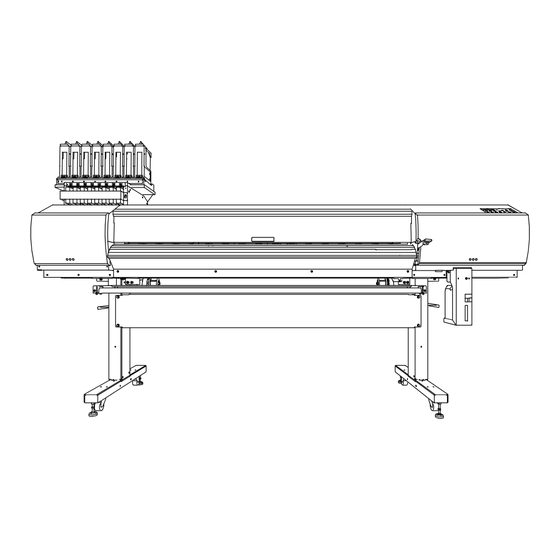
Part Names and Functions Printer Unit Front Subtank slots Ink pouch holder Front cover This is where subtank This is where ink pouches are installed. Leave closed except when loading cartridges are installed. media etc. Operation panel P. 8 "Operation Panel" Right cover Remove this when Left cover... - Page 9 Part Names and Functions Front Cover Interior/Print Head Area Print-head carriage The print heads are equipped inside this. Pinch rollers These clamp the me- dia when the loading lever is lowered. Grit rollers These rollers feed out media toward the front of the machine.
-
Page 10: Operation Panel
Part Names and Functions Operation Panel Illustration in this Part Name Description manual This displays various setting menus and W1200mm Display screen other information. This switches the printer on and off. (To switch the printer off, hold down the Sub power switch switch for one second or longer). -
Page 11: Warning Labels
Part Names and Functions Warning Labels Warning labels are affixed to the machine to make areas of danger immediately clear. The meanings of these labels are as follows. Be sure to heed their warnings. Also, never remove the labels or allow them to become obscured. -
Page 12: Vignettes D'avertissement
Part Names and Functions Vignettes d'avertissement Des vignettes d'avertissement sont apposées pour qu'il soit facile de repérer les zones dangereuses. La signification des vignettes est donnée ci-dessous. Respecter les avertissements. Ne jamais retirer les vignettes et ne pas les laisser s'encrasser. Attention : Risque de pincement Faire attention de ne pas coincer les doigts pendant le chargement du... -
Page 13: Menu List
Menu List Main Menu Press MENU MEDIA SETTING To the [AUTO DISPLAY] menu To the [NAME8] menu MENU PRESET LOAD PRESET LOAD NAME1 LOAD NAME8 To the [NAME1] menu To the [NAME8] menu PRESET SAVE SAVE NAME1 SAVE NAME8 To the [NAME1] menu PRESET AUTO DISPLAY AUTO DISPLAY... - Page 14 Menu List Continue To the [TEST PRINT POS] menu MENU SUB MENU SHEET TYPEプ SUB MENUプ SHEET TYPEプ CLEAR OPAQUE SUB MENU SHEET WIDTHバ SHEET WIDTH 1600mm 1600mm To the [CANCEL] menu SUB MENU SHEET POS. SHEET POS. SAVE SHEET POS. CANCEL To the [SAVE] menu SUB MENU...
- Page 15 Menu List Continue Continue Continue To the [DRAIN BOTTLE] menu SUB MENU MAINTENANCE MAINTENANCE CLEANING MAINTENANCE REPLACE WIPER MAINTENANCE REPLACE FELT MAINTENANCE REPLACE KNIFE MAINTENANCE DRAIN BOTTLE To the [CLEANING] menu SUB MENU TEST PRINT POS TEST PRINT POS SCAN FEED To the [SHEET TYPE] menu To the [NETWORK] menu...
-
Page 16: Language And Unit Menu
Menu List Language and Unit Menu While holding down , switch on the sub power. MENU LANGUAGE ENGLISH LENGTH UNIT INCH TEMP. UNIT 。 。 ° Cleaning Menu Hold down for one second or longer. Press To the [POWERFUL CL.] menu Normal cleaning of all groups CLEANING NOMAL CL. -
Page 17: Dryer Settings Menu
Menu List Dryer Settings Menu Press DRYER... -
Page 18: Important Notes On Handling And Use
Important Notes on Handling and Use This machine is a precision device. To ensure the full performance of this machine, be sure to observe the following important points. Failure to observe them may not only result in loss of performance but may also cause malfunction or breakdown. Printer Unit This machine is a precision device. -
Page 19: Chapter 2 Basic Operation
Chapter 2 Basic Operation Preparing Media ..................18 Types of Media ...................18 Conditions for Usable Media ..............18 Media Storage Environment...............19 Switch On! ...................20 Switch On! ....................20 Sleep Mode (Power-saving Feature) ............20 Loading Media ...................21 Loading Roll Media ..................21 Loading Sheet Media .................37 Performing the Initial Adjustment (Correcting for Misalignment in Bidirec- tional Printing More Precisely) ..............40 Setup of Media ..................42... -
Page 20: Preparing Media
Preparing Media Types of Media In this manual, the paper used for printing is called "media." There are the following main two media types used in this machine. Roll media: Media wound onto a paper tube Sheet media: Media not wound onto a paper tube such as standard-size media Various paper qualities of roll media and sheet media are selectable according to the purpose. -
Page 21: Media Storage Environment
Preparing Media Media Storage Environment Depending on the type of transfer paper, if it is stored in a humid environment for a long time, the coating of the paper may degrade and affect print quality. (In most cases, once the coating degrades, it will not return to its original condition.) Avoid storing transfer paper in humid environments. -
Page 22: Switch On
Switch On! Switch On! WARNING When output is not being performed, remove any loaded media or switch off the sub power. The continued application of heat at a single location may cause the release of toxic gases from the media or pose a fire hazard. Procedure ... -
Page 23: Loading Media
Loading Media Loading Roll Media CAUTION Load roll media correctly. Otherwise, the media may fall and cause injury. CAUTION Roll media weighs about 40 kg (88 lb.). To avoid injury, handle the roll media with care. CAUTION Do not load roll media that weighs more than 40 kg (88 lb.). The machine may tip over because it is incapable of withstanding the weight. - Page 24 Loading Media Fit the paper tube (core) of the media onto the end cap of the media holder (Left). Do not secure the media holder now. Move the media holder (Right) and fit the end cap onto the paper tube (core) of the media.
- Page 25 Loading Media Hold the outer side of the media holder (Left) and position the left edge of the media to align with the marks. When deciding the position, hold the both sides of media holders from the outer sides and move it. Do not hold the media directly to move.
- Page 26 Loading Media Pass the media through the machine and secure the media holders. Pass the leading edge of the media between the grit rollers and the pinch rollers. Pass the media over the top of the feed adjuster bar. Pinch roller Grit rollers Media...
- Page 27 Loading Media Open the front cover. Do not open the front cover until instructed to do so. Grip Front cover Pull out the media over the platen. Make sure the right edge of the media is in line with the guide line. Guide line ...
- Page 28 Loading Media Hold the media at the center and pull it out, being sure to keep it straight and all areas of the media to be taut. Make sure the right edge of the media is in line with the guide line. ...
- Page 29 Loading Media Clamp the edges of the media with the media clamps. The media clamps are magnetic, and the left and right clamps are distinct. Refer to the figure and install the clamps in the correct positions, making sure not to confuse right and left. Line up the edge of the media with the centers...
- Page 30 Loading Media Load a paper tube onto the take-up system, and switch on the take-up system power. This section describes parts that use the take-up system. These instructions describe how to use TUC-3. If using a take-up system other than TUC-3, refer to the user’s manual of the take-up system you are using. ...
- Page 31 Loading Media Secure the motorized media holder. Secure the motorized media holder firmly using the securing screws. Fit the paper tube (core) onto the end cap (Right). Fit the paper tube securely right to the end of the end cap. ...
- Page 32 Loading Media Adjust the position of the media. Set the AUTO switch on the take-up unit. It is recommended that you use the BACKWARD setting when using the take-up unit with the machine. When using the TUC-3 as the take-up system, it is not possible to use it with the FORWARD setting if it is adjusted for use with the BACKWARD setting during installation.
- Page 33 Loading Media Switch on the sub power. Sub power switch The print-head carriage moves and detects the width of the media. This operation is called initialization. When initialization ends, lights, and the width of the media is displayed on the screen. ...
- Page 34 Loading Media Loosen the securing screw of the motorized media holder. Adjust the position of the media holder. Move both media holders so that it is possible to see around 20 mm (0.79 in.) of the paper tube (core) from the right edge of the media.
- Page 35 Loading Media Secure the motorized media holder in place. Secure the motorized media holder firmly using the securing screws. Push the media holder (Left) in the direction of the motorized media holder and securely fasten the end cap to the paper tube (core). Push the media holder firmly until the gap between the media holder and end cap at either end is filled in as shown in the figure.
- Page 36 Loading Media Secure the media on the paper tube (core). When using the BACKWARD setting Pass the media around the inner side of the paper tube (core). When using the FORWARD setting Pass the media toward the back of the machine from the outside of the paper tube (core).
- Page 37 Loading Media When using the BACKWARD setting While holding the media, slowly lower the dancer bar forward. Stop lowering the dancer bar when the paper tube (core) starts rotating. When doing so, do not move the hand holding the media away. After this, you will secure the media on the paper tube (core) in this position. When using the FORWARD setting (Go round to the back of the machine and,) while holding the media, slowly lower the dancer bar forward.
- Page 38 Loading Media Attach the center and both ends of the media to the paper tube (core) using adhesive tape (three locations in total). While pulling the media so that it does not sag, secure the center of the media. While pulling the media from the center toward the outer edges, and fix the left and right edges.
-
Page 39: Loading Sheet Media
Loading Media Loading Sheet Media Procedure Switch off the sub power. Open the front cover. Do not open the front cover until instructed to do so. Draw the media holders to both left and right ends respectively. Move them to a location where they don’t disturb the media when the media is hung down from the rear of the machine. - Page 40 Loading Media Align the front edge of the media with the location shown in the figure. Make sure the right edge of the media is in line with the guide line. Guide line Lower the loading lever (front side) to secure the media in place.
- Page 41 Loading Media Attach the right and left media clamps. Line up the edges of the media with the centers of the holes of the media clamps. The media clamps are magnetic, and the left and right clamps are distinct. Refer to the figure and install the clamps in the correct positions, making sure not to confuse right and left.
-
Page 42: Performing The Initial Adjustment (Correcting For Misalignment In Bidirectional Printing More Precisely)
Loading Media Performing the Initial Adjustment (Correcting for Misalignment in Bidirectional Printing More Precisely) Perform the initial adjustment of this machine. This adjustment must be performed in the following cases: When using this machine for the first time When changing the media to use ... - Page 43 Loading Media Enter the correction values that you read. Enter the corresponding correction values for H1 and H2. Press DETAIL SETTING SETTING NO.1 Press to select H1 or H2. H2 H1 Press to select the correction value. Select the correction values that you read in step When you have finished setting the correction values, press This completes the configuration of [SETTING NO.
-
Page 44: Setup Of Media
Setup of Media About "MEDIA SETTING" menu To ensure the optimal printing according to the media size and type, various setting items are provided in the machine. The machine provides the "MEDIA SETTING" menu that guides you through these settings in an interactive mode. - Page 45 Setup of Media Set the dryer temperature. Press to set the temperature. DRYER 30゜C 40゜C Recommended temperature: 40°C Press to confirm your entry. For the individual setting method and the description of this setting item, refer to the following section. ...
- Page 46 Setup of Media Close the front cover. For the individual setting method and the description of this setting item, refer to the following section. P. 106 "Adjusting Print Head Height to Match Media Thickness" Perform position correction of the feed direction (reduce horizontal stripes). Feed direction means the feed direction of the media.
- Page 47 Setup of Media To confirm again/adjust again REDO ADJ.? [YES] DONE Press to select [YES]. Press to confirm your entry. The test pattern of feed correction is printed again. Go back to step and set again. To go to the next after correction is completed Press to select [DONE].
- Page 48 Setup of Media To confirm again/adjust again REDO ADJ.? [YES] DONE Press to select [YES]. Press to confirm your entry. The test pattern of bidirectional correction is printed again. Go back to step and set again. To go to the next after correction is completed Press to select [DONE].
- Page 49 Setup of Media Save the setting as preset. Press to select [SAVE]. PRESET [SAVE] NEXT Press to confirm your entry. If you select [NEXT], the screen in step is displayed, and the set- tings you have selected up to this point are not saved as a preset. How- ever, they will remain as the current settings values for the machine.
-
Page 50: Print
Print Setting the Printing-start Location The output-start location can be set to any location you desire. (It is possible to print even if this setting is not configured.) Note, however, that this setting must be made for each individual page. When the printing of one page finishes, the output-start location returns to its default value. -
Page 51: Printing Tests And Normal Cleaning
Print Output area Vertical (feed) Output-start location direction output- start location Horizontal (scan) direction output- start location When the location is set, press lights. When the screen displays the character "B" together W1100mm with the output-possible width at the location, setting is complete. Printing Tests and Normal Cleaning Before you carry out actual printing, perform a printing test to ensure no dot drop-out occurs. - Page 52 Print Press to select "SCAN." TEST PRINT POS SCAN FEED Press to enable the setting. Press to go back to the original screen. Perform a printing test Setting the Print-start Location. P. 48 "Setting the Printing-start Location" ...
- Page 53 Print Check for the group with dot drop-out by viewing the printing-test results. With normal cleaning, only the group of print heads having dot drop-out is cleaned. Printing-test results If the printing-test results are difficult to interpret Examine the results from different angles in a well-lit location.
-
Page 54: Getting Ready To Receive Data From A Computer
Print Getting Ready to Receive Data from a Computer When P. 21 "Loading Media" and P. 42 "Setup of Media" are completed, get the machine ready to receive the data from the computer. CAUTION Never touch the print-head carriage while printing is in progress. The print-head carriage moves at high speed. -
Page 55: Starting Printing
Print Starting Printing When P. 52 "Getting Ready to Receive Data from a Computer" is completed, it is possible to start printing. To print, the following procedure is required Creating printing data Create printing data using application software such as Adobe Illustrator. For information on how to create the data, refer to the documentation of your application software. -
Page 56: If A Cover Opens During Operation
Print If a Cover Opens during Operation If the front cover, left cover, or right cover (hereafter collectively referred to as “covers”) is opened during print- ing or any other operation where the print-head carriage (hereafter referred to as “carriage”) is moving, the machine will perform an emergency stop. -
Page 57: Cutting Off The Media
Print Cutting Off the Media Procedure Remove the left and right media clamps. Lift the media clamps up to remove them. Close the front cover. Check that is lit. Hold down for one second or longer. The media is cut off. -
Page 58: Transfer Conditions
Print Cutoff Operations When the media clamps are attached, the screen shown REMOVE on the left appears. Open the front cover, remove the MEDIA CLAMPS left and right media clamps, and then press Be sure to remove the media clamps. If you attempt to perform the cutoff operation while the media clamps are attached, the machine will detect them and interrupt the operation. -
Page 59: Switch Off
Switch Off Switch Off WARNING When output is not being performed, remove any loaded media or switch off the sub power. The continued application of heat at a single location may cause the release of toxic gases from the media or pose a fire hazard. Procedure ... -
Page 61: Chapter 3 Maintenance: Keeping The Machine In Good Working Order
Chapter 3 Maintenance: Keeping the Machine in Good Working Order Ink Pouch Replacement ..............60 Out-of-ink Warnings ...................60 Ink Pouch Replacement ................61 Maintenance That Should Be Performed Daily ........63 Disposing of Discharged Fluid ..............63 Cleaning .....................65 Care and Maintenance of the Print Heads ..........66 When Normal Cleaning Is Not Effective ..........67 Medium Cleaning ..................67 Powerful Cleaning ..................68... -
Page 62: Ink Pouch Replacement
Ink Pouch Replacement Out-of-ink Warnings P. 61 "Ink Pouch Replacement" If Using 4 Colors (CMYK) Indicates that the ink pouch/subtank is currently in use. Flashing Indicates that the ink pouch/subtank is empty. Indicates that the ink pouch/subtank is not currently in use. -
Page 63: Ink Pouch Replacement
Ink Pouch Replacement Ink Pouch Replacement Precautions regarding ink pouch replacement Be sure to replace each pouch with an item of identical type and color. Install a pouch in each port. If there is a port that does not have a pouch installed, ink may dry up or air may enter the ink path, resulting in malfunction. - Page 64 Ink Pouch Replacement Do not raise an ink pouch holder if there is no ink pouch is installed in it. Doing so may cause air to enter the ink path, resulting in malfunction. It may take some time to restore operation in the event of malfunction.
-
Page 65: Maintenance That Should Be Performed Daily
Maintenance That Should Be Performed Daily Disposing of Discharged Fluid The drain bottle collects discharged fluid. Dispose of collected material CHECK DRAIN BOTTLE before the bottle becomes full. The message shown in the figure appears when a certain amount of discharged fluid has collected in the bottle. Follow the procedure below to discard the discharged fluid. - Page 66 Maintenance That Should Be Performed Daily Press RESET DRAIN COUNTER Press , then to go back to the original screen. WARNING Never place discharged fluid or ink near an open flame. Doing so may cause a fire. CAUTION To store discharged fluid temporarily, place it in the included drain bottle or in a durable sealed container such as a metal can or polyethylene tank, and cap the container tightly.
-
Page 67: Cleaning
Maintenance That Should Be Performed Daily Cleaning WARNING Never use gasoline, alcohol, thinner, or any other flammable material. Doing so may cause a fire. CAUTION Before attempting cleaning, switch off the sub power and wait until the platen and dryer cool (approximately 30 minutes). Sudden movement of the machine may cause injury, or hot components may cause burns. -
Page 68: Care And Maintenance Of The Print Heads
Maintenance That Should Be Performed Daily Care and Maintenance of the Print Heads To keep a stable printing condition at all times, the print heads need to be maintained. There are maintenance tasks that should be performed daily and those that should be performed periodically. Daily Care and Maintenance ... -
Page 69: When Normal Cleaning Is Not Effective
When Normal Cleaning Is Not Effective Medium and powerful cleaning consume more ink than normal cleaning, and overly frequent use may damage the print heads themselves. Avoid performing more than necessary. Medium Cleaning When problems such as dot drop-out are not resolved by normal cleaning (P. 49 "Printing Tests and Normal Cleaning"), perform the more forceful "medium cleaning"... -
Page 70: Powerful Cleaning
When Normal Cleaning Is Not Effective Press The screen shown in the figure appears, and then cleaning starts. CLEANING... >>>>> 01:45 The (approximate) remaining time for the procedure is displayed on the screen. ("01:45" = "1 minute and 45 seconds") MEDIUM CL. -
Page 71: If Colors Are Uneven
If Colors Are Uneven Mixing the Ink by Shaking the Ink Pouch If ink components precipitate in the ink pouch, colors may be uneven (unevenness in printed colors). If colors are uneven, remove the ink pouches and shake them gently. ... - Page 72 If Colors Are Uneven Press several times to display the screen shown INK CONTROL LIGHT CHOKE CL. on the left. Press If the message [EMPTY DRAIN BOTTLE] is displayed on the screen When the screen shown on the left is displayed, discard the EMPTY DRAIN BOTTLE discharged fluid.
-
Page 73: Maintenance That Should Be Performed More Than Once A Month
Maintenance That Should Be Performed More than Once a Month When Manual Cleaning Becomes Necessary Perform Manual Cleaning Once a Month or More To keep the stable printing condition at all times, perform manual cleaning once a month or more. Manual cleaning takes approximately 10 minutes. -
Page 74: Manual Cleaning
Maintenance That Should Be Performed More than Once a Month Manual Cleaning Important notes on this procedure Before attempting this operation, remove any media. To prevent the print heads from drying out, finish this procedure in 30 minutes or less. A warning beep sounds after 30 minutes. - Page 75 Maintenance That Should Be Performed More than Once a Month Press several times until the screen on the left SUB MENU MAINTENANCE appears. Press Press MAINTENANCE CLEANING When the screen shown on the left is displayed, open OPEN COVER R the right cover.
- Page 76 Maintenance That Should Be Performed More than Once a Month Close the right cover. CLOSE COVER R When the screen shown on the left is displayed, open OPEN COVER R the right cover. Preparations are complete when this screen appears. FINISHED? ...
- Page 77 Maintenance That Should Be Performed More than Once a Month Clean the area around the print heads with the cleaning stick. Open the left cover. OPEN COVER L Remove the bolt ( ), and then remove the cut rail ( REMOVE CUT RAIL Press...
- Page 78 Maintenance That Should Be Performed More than Once a Month Clean the locations shown in the following figure. Be especially careful to clean away any fibrous dust (lint). Area to clean During this work, be careful not to touch the surfaces of the print heads directly. Clean only the frame.
- Page 79 Maintenance That Should Be Performed More than Once a Month Reattach the left and right covers, and finish manual cleaning mode. Close the left cover. CLOSE COVER L Close the right cover. CLOSE COVER R Open the left cover. OPEN COVER L ...
-
Page 80: Maintenance That Should Be Performed Every Six Months
Maintenance That Should Be Performed Every Six Months Refreshing Subtanks (REFRESH SUBTANKS) Refresh the subtanks once every six months to resolve issues with ink components precipitating in the sub- tanks. If this procedure is not performed once every six months, print quality may be adversely affected, e.g., printed colors may be uneven. - Page 81 Maintenance That Should Be Performed Every Six Months After discarding the discharged fluid, press Precautions for the operations to follow Take care not to drop ink pouches. During this work, move the ink pouch holders slowly. If you let go of the ink pouch holders partway through moving them, they will be subjected to a strong impact, which may cause the ink to leak.
- Page 82 Maintenance That Should Be Performed Every Six Months Finish refreshing the subtanks. SET INK POUCH 12345678 Install all the ink pouches. Take care to use the right colors. Attach the stoppers. Take care not to crush the ink pouches. ...
-
Page 83: When Problems Such As Dot Drop-Out Are Not Fixed
When Problems Such as Dot Drop-Out Are Not Fixed When Problems Such as Dot Drop-Out Are Not Fixed Perform the procedure below if ink discharge issues such as dot drop-out are not corrected after performing cleaning using the cleaning function (normal, medium, powerful) or manual cleaning. A large amount of ink will be discharged during this operation. - Page 84 When Problems Such as Dot Drop-Out Are Not Fixed Cleaning the print head surface as an emergency measure When dot drop-out or dot deflection is not improved even if cleaning is performed several times, you can clean the surface of the print heads as an emergency measure. The print head surface (nozzle surface) is a very delicate mechanism, so work must be performed carefully and cautiously.
-
Page 85: Replacing Consumable Parts
Replacing Consumable Parts Replacing the Wiper The wiper is a component that is used for cleaning the print heads. When the screen displays a message like the one shown below, it is time to replace the items. There are two wipers. Replace both wipers with new ones. TIME FOR WIPER REPLACE For information about purchasing wipers, contact your authorized Roland DG Corp. - Page 86 Replacing Consumable Parts Replace the wiper. Open the right cover. FINISHED? Preparations are complete when this screen appears. Touch the location shown in the figure to discharge any static electricity. Replace the first wiper. Removing an old wiper If the area is dark and difficult Pull up and Tweezers (included)
- Page 87 Replacing Consumable Parts Press Close the right cover. CLOSE COVER R Open the right cover. OPEN COVER R Preparations are complete when this screen appears. FINISHED? Replace the second wiper. The replacement procedure is the same as for the first wiper. Refer to the illustration shown in step Exit the wiper replacement menu.
-
Page 88: Replacing The Felt Wiper
Replacing Consumable Parts Replacing the Felt Wiper The felt wiper is a component that is used for cleaning the print heads. When the screen displays a message like the one shown below, it is time to replace the items. There are two felt wipers. Replace both felt wipers with new ones. - Page 89 Replacing Consumable Parts Replace the felt wiper. Open the right cover. Preparations are complete when this screen appears. FINISHED? Touch the location shown in the figure to discharge any static electricity. Open the front cover. Replace the first felt wiper. Removing an old felt wiper If the area is dark and difficult Pull up and out.
- Page 90 Replacing Consumable Parts Close the front cover. Press Close the right cover. CLOSE COVER R Open the right cover. OPEN COVER R Preparations are complete when this screen appears. FINISHED? Open the front cover. Replace the second felt wiper.
-
Page 91: Replacing The Separating Knife
Replacing Consumable Parts Replacing the Separating Knife If the separating knife becomes dull, replace it with the included replacement knife. CAUTION Be sure to perform operations as specified by the instructions, and never touch any area not specified in the instructions. Failure to observe these instructions may cause the machine to move suddenly, resulting in injury. - Page 92 Replacing Consumable Parts Replace the separating knife. Remove the separating knife. Loosen the screw until it slips out. Grasp the screw portion, and slowly pull ② ② in the direction of the arrow. When doing this, do not pull it toward you. ①...
-
Page 93: When Not In Use For A Prolonged Period
When Not in Use for a Prolonged Period Keep Performing Maintenance Switch on the power once a month Switch on the sub power once a month. When you turn on the power, the machine automatically performs some operations such as those to keep the print heads from drying out. Leaving the machine unused for a prolonged period may damage the print heads, so be sure to switch on the power to perform these automatic operations. -
Page 95: Chapter 4 Advanced Functions
Chapter 4 Advanced Functions Fully Utilizing the Preset Function............94 Saving Various Settings as a Name Assigned Preset ........94 Loading a Saved Preset ................95 Automatic Loading of a Saved Preset When Media Is Loaded ....96 Using the Dryer ...................97 What is the Dryer? ..................97 Setting the Temperature of the Dryer ............98 Dryer Control While Idling ................99 Drying the Trailing Edge of the Printing Area on the Dryer ......100... -
Page 96: Fully Utilizing The Preset Function
Fully Utilizing the Preset Function Saving Various Settings as a Name Assigned Preset Procedure Press Press to display the screen shown on the left. MENU PRESET Press , then Press PRESET SAVE Press to select one option from SAVE NAME1 NAME1 to NAME8. -
Page 97: Loading A Saved Preset
Fully Utilizing the Preset Function [DRYER] P. 98 "Setting the Temperature of the Dryer" [PREHEATING] P. 99 "Dryer Control While Idling" [FEED FOR DRY] P. 100 "Drying the Trailing Edge of the Printing Area on the Dryer" [DRYING TIME] ... -
Page 98: Automatic Loading Of A Saved Preset When Media Is Loaded
Fully Utilizing the Preset Function Description This loads a saved preset. You can select any one of eight types of presets. (When no names have been assigned, select from among NAME1 through NAME8.) If you load a preset while is lit, starts flashing. -
Page 99: Using The Dryer
Using the Dryer What is the Dryer? This machine is equipped with a dryer for drying the ink. You can adjust the temperature settings to match the type of media and the printing speed. Dryer This is used to speed up the drying of the ink. -
Page 100: Setting The Temperature Of The Dryer
Using the Dryer Setting the Temperature of the Dryer Procedure Press The current temperature is displayed. Press a second time. Press to select the unit. DRYER 40 40 Press to set the temperature. DRYER 40 30 You can also set the temperature to "OFF."... -
Page 101: Dryer Control While Idling
Using the Dryer Description With the default settings, simply switching on the power does not make the dryer warm up to the set tem- perature. The temperature rises to the set temperature when the media is loaded correctly and lights. You can also make this setting in the software RIP. When you have made the setting in the software RIP, the software RIP's setting is used. -
Page 102: Drying The Trailing Edge Of The Printing Area On The Dryer
Using the Dryer Drying the Trailing Edge of the Printing Area on the Dryer Procedure Hold down and press Press to display the screen shown on the left. HEATER MENU FEED FOR DRY Press Press to select "ENABLE." FEED FOR DRY DISABLE ENABLE Press... -
Page 103: Setting The Drying Time After Printing
Using the Dryer Setting the Drying Time after Printing Procedure Hold down and press Press Press to display the screen shown on the left. HEATER MENU DRYING TIME Press Press to select the drying time. DRYING TIME 0min 10min Press... -
Page 104: Fully Utilizing The Correction Function
Fully Utilizing the Correction Function Correcting for Misalignment in Bidirectional Printing Procedure Press Press several times to display the screen shown MENU ADJUST BI-DIR on the left. Press Press ADJUST BI-DIR TEST PRINT A test pattern is printed. When printing ends, press , and then press ... -
Page 105: Reducing Horizontal Bands (Feed Correction Function)
Fully Utilizing the Correction Function Reducing Horizontal Bands (Feed Correction Function) Procedure If using roll media, check that the media is not sagging. Press Press several times to display the screen shown MENU CALIBRATION on the left. Press ... -
Page 106: Correcting Media Skew
Fully Utilizing the Correction Function Correcting Media Skew Perform this correction when horizontal stripes cannot be eliminated even after performing the operations in P. 103 "Reducing Horizontal Bands (Feed Correction Function)". Procedure If using roll media, check that the media is not being wound improperly. If the media is not wound correctly, fix and re-set the media. - Page 107 Fully Utilizing the Correction Function Check the test results to determine the correction values. Choose the value that produces the least misalignment of the 2 lines. When you cannot choose between two numbers, select a value between them. “R” means “right, ” and “L” means “left. ” For example, if the line marked “L2.5” has the least misalignment, this means that there is a 2.5 mm (98.4 mil) misalignment to the left.
-
Page 108: Accommodating Different Media Types And Conditions
Accommodating Different Media Types and Conditions Adjusting Print Head Height to Match Media Thickness Procedure Press Press several times to display the screen shown MENU HEAD HEIGHT on the left. Press When the screen shown on the left is displayed, open HEAD HEIGHT the front cover. -
Page 109: Using Transparent Media
Accommodating Different Media Types and Conditions Using Transparent Media Set the media type to "CLEAR." Raise the loading lever. Press Press several times to display the screen shown MENU SUB MENU on the left. Press twice. Press to select "CLEAR."... - Page 110 Accommodating Different Media Types and Conditions Press to move the print-head carriage (base point mark) to the Base point mark right edge of the media. The position indicated by the arrow of the base point mark is set as the position of the right edge of the media If a fixed period of time passes while the setting procedure is in progress, the menu is forcefully terminated.
-
Page 111: Using Hard-To-Dry Media
Accommodating Different Media Types and Conditions Using Hard-to-Dry Media Procedure Press Press several times to display the screen shown MENU SUB MENU on the left. Press Press several times to display the screen shown SUB MENU SCAN INTERVAL on the left. -
Page 112: Changing The Range Of Print-Head Carriage Movement
Accommodating Different Media Types and Conditions Press to select a value. VACUUM POWER AUTO Press to confirm your entry. When the media is flimsy and cannot move smoothly, decreasing this value (reducing 0%–100% the suction force) may resolve the problem. AUTO The strongest suction force will always be used. -
Page 113: Expanding The Printing Area By Reducing The Margins
Accommodating Different Media Types and Conditions Description Fixing the width that the print-head carriage moves can help reduce uneven colors. When this setting is set to "OFF," the movement of the print-head carriage is minimized. This does save printing time, but because the speed of media movement is no longer constant, colors may be uneven. -
Page 114: Preventing Soiling Of The Media And Dot Drop-Out
Accommodating Different Media Types and Conditions Preventing Soiling of the Media and Dot Drop-Out Procedure Press Press several times to display the screen shown MENU SUB MENU on the left. Press Press several times to display the screen shown SUB MENU PERIODIC CL. -
Page 115: Using Sticky Media
Accommodating Different Media Types and Conditions Using Sticky Media Procedure Press Press several times to display the screen shown MENU SUB MENU on the left. Press Press several times to display the screen shown SUB MENU MEDIA RELEASE on the left. -
Page 116: Printing With Crop Marks
Printing with Crop Marks Printing with Crop Marks Use your software RIP to configure the settings for printing crop marks. For information on how to make the settings, refer to the documentation for the software RIP you are using. Alignment marks and symbols drawn using graphics software cannot be used as crop marks. -
Page 117: Using The Media Take-Up System
Using the Media Take-Up System Using the Media Take-up System The media take-up system ("take-up system") is an optional item. For information on how to assemble and install the take-up system, refer to the user’s manual of the take- up system. -
Page 119: Chapter 5 To Administrators
Chapter 5 To Administrators Output Operation Management ............118 Printing a System Report ................. 118 Determining What Happens When Ink Runs Out........118 Displaying the Amount of Media Remaining ..........119 Making Sure to Verify the Setting for the Amount Remaining Every Time the Media Is Changed ....................120 Printing the Amount of Remaining Media ..........121 System Management of Printer ............122... -
Page 120: Output Operation Management
Output Operation Management Printing a System Report This prints system information, including a list of setting values. Procedure Press Press several times to display the screen shown MENU SUB MENU on the left. Press Press several times to display the screen shown SUB MENU SYSTEM REPORT on the left. -
Page 121: Displaying The Amount Of Media Remaining
Output Operation Management Description When “STOP” is selected, printing pauses, so colors may be uneven. Ensure that the remaining ink is sufficient before you begin printing. When "CONT" is selected, printing does not stop even if ink runs out completely. To replace an ink pouch, wait until printing ends or press to pause printing. -
Page 122: Making Sure To Verify The Setting For The Amount Remaining Every Time The Media Is Changed
Output Operation Management Making Sure to Verify the Setting for the Amount Remaining Every Time the Media Is Changed SET LENGTH Set the machine to display every time the media is changed. 0.0m 25.0m Procedure Press Press to display the screen shown on the left. MENU SHEET REMAIN Press... -
Page 123: Printing The Amount Of Remaining Media
Output Operation Management Printing the Amount of Remaining Media This prints the amount of media remaining that is displayed at the top menu. Procedure Press Press to display the screen shown on the left. MENU SHEET REMAIN Press ... -
Page 124: System Management Of Printer
System Management of Printer Setting Menu Language and Units of Measurement This sets the language and units of measurement displayed on the display screen of the operation panel. Procedure Hold down and switch on the sub power. Press to select the display (menu) MENU LANGUAGE ENGLISH... -
Page 125: Viewing System Information
System Management of Printer Viewing System Information Note: For information on how to set up a network, see the "Setup Guide." Procedure Press Press several times to display the screen shown MENU SYSTEM INFO. on the left. You can view the following information: [MODEL]: Model name [SERIAL NO.]: Serial number [INK]: Ink type... -
Page 126: Returning All Settings To Their Factory Default Values
System Management of Printer Returning All Settings to Their Factory Default Values This menu returns all settings to their factory defaults. However, the settings for [MENU LANGUAGE], [LENGTH UNIT], and [TEMP. UNIT] are not returned to their factory default values. Procedure ... -
Page 127: Changing Installation Location
Changing Installation Location Before changing the installation location of the machine, consult your authorized Roland DG Corporation dealer. Roland service technician will move the machine and make adjustments afterwards. * The feed adjuster must be adjusted after the machine has been moved even if it has only been moved a short distance, e.g., to a different location on the same floor. -
Page 129: Chapter 6 Read This Chapter Whenever You Face A Problem (Faq)
Chapter 6 Read This Chapter Whenever You Face a Problem (FAQ) Attractive Printing is Impossible ............128 Printed Results Are Coarse or Contain Horizontal Stripes .......128 Colors Are Unstable or Uneven..............129 The Media Becomes Soiled When Printed ..........130 Color Mixing Occurs .................131 A Media Jam Occurs! ................132 The Media Has Jammed ................132 Media Feed Is Not Smooth ...............133... -
Page 130: Attractive Printing Is Impossible
Attractive Printing is Impossible Printed Results Are Coarse or Contain Horizontal Stripes Do the print heads show dot drop-out? Carry out a printing test and make sure no dot drop-out occurs. If dot drop-out is present, perform cleaning of the print heads. P. -
Page 131: Colors Are Unstable Or Uneven
Attractive Printing is Impossible Is the media loaded correctly? If the media is not loaded correctly or media feed is not smooth, printing results may be adversely affected. Load the media correctly. P. 21 "Loading Media" P. 133 "Media Feed Is Not Smooth" ... -
Page 132: The Media Becomes Soiled When Printed
Attractive Printing is Impossible Is the media wrinkled? If the media is wrinkled and comes loose from the platen, colors may be uneven or printing results may be adversely affected. P. 133 "Media Wrinkles or Shrinks" Have you not printed for a while? If printing is not performed for several days, printed colors may become unstable or uneven, e.g., when color density is inconsistent, even if the same data is printed with the same settings. -
Page 133: Color Mixing Occurs
Attractive Printing is Impossible Color Mixing Occurs Has an ink pouch of the wrong color been installed by mistake? As soon as an ink pouch is installed, ink flows out of the ink pouch into the ink path. Therefore, if an ink pouch is installed incorrectly, ink mixes inside the ink path even if the pouch is removed immediately. -
Page 134: A Media Jam Occurs
A Media Jam Occurs! The Media Has Jammed If an error message is displayed because the media has jammed, immediately correct the prob- lem. Failure to do so may damage the print heads. P. 144 "[MOTOR ERROR TURN POWER OFF]" ... -
Page 135: Media Feed Is Not Smooth
Media Feed Is Not Smooth A variety of problems can occur if the media feed is not smooth. This can cause such problems as poor printing results, contact with the media by the print heads, misaligned positioning, or media jams. Take action as follows. Media Wrinkles or Shrinks Are the media clamps attached? When you are performing printing, be sure to attach the media clamps. -
Page 136: Media Feeding Is Not Straight
Media Feed Is Not Smooth Media Feeding Is Not Straight Are the grit rollers dirty? Check to make sure the grit rollers are free of buildup of foreign material such as media scraps. P. 65 "Cleaning" Is the media loaded straight and securely? Feed is not smooth when the media is not straight or is tensioned unevenly on the left and right. -
Page 137: Why Has The Print-Head Carriage Stopped Moving
Why Has the Print-Head Carriage Stopped Moving? If the print-head carriage stops over the platen, take action immediately to prevent the print heads from drying out. What to Do First Switch the sub power off and then back on again. If the media is jammed, also remove the media. - Page 138 Why Has the Print-Head Carriage Stopped Moving? Gently move the print-head carriage to the home position by hand. Stopping at the place where the audible click is heard locks the print-head carriage in place. Gently apply pressure from the right side to make sure the print-head carriage does not move to the left.
-
Page 139: Other Problems
Other Problems The Machine Does Not Move Are the cables connected? Connect the cables securely. "Setup Guide" Is the power switched on? Switch on the machine's main power, then press the sub power switch and make sure the sub power switch lights up. - Page 140 Other Problems Has the ink run out? 1 2 3 4 5 6 7 8 When the screen shown above is displayed, print data cannot be accepted. If the screen shown above is displayed during printing, the behavior of the machine depends on the [EMPTY MODE] setting.
-
Page 141: Cannot Cut Off The Media
Other Problems Cannot Cut Off the Media Is the separating knife installed? If the separating knife is not installed, you cannot cut off the media. P. 89 "Replacing the Separating Knife" Is the cut rail installed? If the cut rail is not installed, you cannot cut off the media. The cut rail is removed when performing manual ... -
Page 142: A Message Appears
A Message Appears These are the main messages that appear on the machine's display to prompt correct operation. They do not indicate any errors. Follow the prompts and take action accordingly. [PRESS THE ENTER KEY TO CONTINUE OPERATION] If the front cover, left cover, or right cover (hereafter collectively referred to as “covers”) is opened during printing or any other operation where the print-head carriage is moving, the printer will perform an emergency stop. - Page 143 A Message Appears [NOW HEATING... NOW PROCESSING..] Wait until the dryer reaches the set temperature. Printing starts when lights. You can stop printing by holding down for one second or longer while this is displayed. Pressing makes printing start immediately without waiting to reach the set temperature. [TIME FOR MAINTENANCE] It is time to clean the printer heads manually.
-
Page 144: An Error Message Appears
An Error Message Appears This describes the error messages that may appear on the machine's display and how to take action to remedy the problem. If the action described here does not correct the problem or if an error message not described here appears, contact your authorized Roland DG Corp. dealer. [CLOSE COVER (FRONT COVER/COVER L/COVER R)] Close the front, left, and right covers. - Page 145 An Error Message Appears raising the temperature. To continue waiting for the temperature to rise, press . To start printing immediately, press [SERVICE CALL xxxx] An unrecoverable error occurred, or part replacement that must be performed by a service technician is required. Note the number displayed on the display screen, then switch off the sub power.
- Page 146 An Error Message Appears [AVOIDING DRY-UP TURN POWER OFF] The print heads were forced to the home position to prevent them from drying out. Operation cannot be continued. Switch the sub power off, then back on. [SET HEAD HEIGHT TO xxx] The height of the print heads is lower than the height specified in the software RIP.
- Page 147 An Error Message Appears [MEMORY ERROR TURN POWER OFF] An error occurred while data was being written to or read from memory. The operation cannot be continued. Switch the sub power off by holding down the switch for one second or longer, and then switch the sub power back on again.
-
Page 149: Chapter 7 Main Specifications
Chapter 7 Main Specifications Printing Area ..................148 Maximum Printing Area and Margins ............148 Maximum Printing Area When Using Crop Marks ........149 Media-Cutoff Location during Continuous Printing ........149 Locations of Power Rating and Serial Number Labels .....150 Specifications ..................151... -
Page 150: Printing Area
Printing Area Maximum Printing Area and Margins Max. 1,615 mm (63.6 in.) Trailing edge of media Media 90 mm (3.5 in.) Media clamp Media clamp Maximum printing area Right margin (*1)(*2) Left margin (*1) Max. 200,000 mm (7,874 in.) 75 mm (3 in.) Leading edge of media Origin of printing coordinates A: Setting of the [SIDE MARGIN] menu item (5 mm, 10 mm [default setting], or 25 mm (0.2 in.,... -
Page 151: Maximum Printing Area When Using Crop Marks
Printing Area Maximum Printing Area When Using Crop Marks The maximum printing area when crop marks are used is reduced from the maximum printing area when crop marks are not used by an amount equal to the crop marks. 12.5 mm (0.5 in.) 12.5 mm (0.5 in.) 10 mm (0.4 in.) 10 mm (0.4 in.) -
Page 152: Locations Of Power Rating And Serial Number Labels
Locations of Power Rating and Serial Number Labels Right side Serial number This is required when you seek main- tenance, servicing, or support. Never peel off the label or let it get dirty. Power rating Use an electrical outlet that meets the requirements for voltage, frequency, and amperage given here. -
Page 153: Specifications
Specifications XT-640 Printing technology Piezoelectric inkjet Media Width 259 to 1,625 mm (10.2 to 64 in.) Thickness Max. 1.0 mm (39 mil) Roll outer Maximum 210 mm (8.3 in.) diameter Roll weight Maximum 40 kg (88 lb.) Core diameter 76.2 mm (3 in.) or 50.8 mm (2 in.) (*1) Printing width (*2) Maximum 1,615 mm (63.6 in.) - Page 156 R2-160520...
Need help?
Do you have a question about the Texart XT-640 and is the answer not in the manual?
Questions and answers