Table of Contents
Advertisement
Advertisement
Table of Contents

Summary of Contents for Zonar V3
- Page 1 REV: 07/31/12...
-
Page 2: Introduction
Contact Zonar at 1-877-843-3847 or by email at customercare@zonarsystems.com. Thank you, Andre J Horochiwsky Technical and Training Manager – Zonar Systems As Zonar Systems is continuously improving the Product, Zonar may make changes to the Product at any time which may not be reflected in this document. -
Page 3: Table Of Contents
Warranty & Notices - FCC Compliance ..........26 Notes....................27 © 2012 Zonar Systems • EVIR, ZPass,Ground Traffic Control and V3 are trademarks of Zonar Systems. All Rights Reserved. Products and services protected by one or more of the following US patents: 6,671,646;... -
Page 4: System Overview
SYSTEM OVERVIEW CELL TOWER INTERNET CUSTOMER ZONAR Secure Servers Encrypted Data Transmissions On-Site Location Real-Time Delivery of Engine Condition and Performance Data, Driver Performance and Location... -
Page 5: V3 Equipment
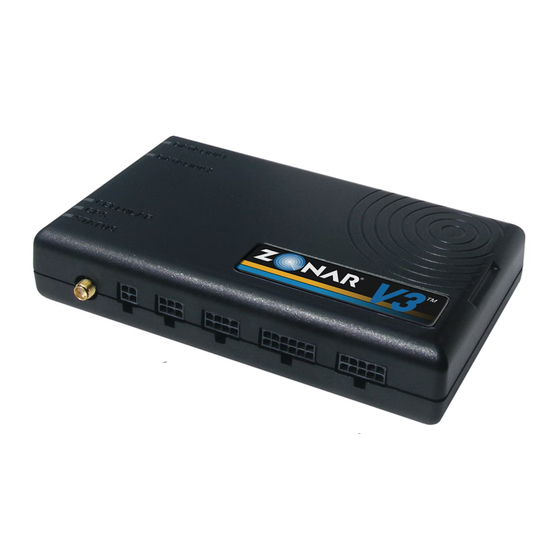
V3™ EQUIPMENT Base Equipment A. V3 GPS Unit B. V3 Mounting Plate and Mounting Screws (Provided) C. GPS Antenna (Optional) D. GPS Antenna Aluminum Mount Plate and Screws (Optional - used for non-magnetic rooftop GPS Antenna installs) Note: See page 14 for detailed information on GPS antenna... -
Page 6: Optional Equipment: Evir
® OPTIONAL EQUIPMENT: EVIR A. 2010 RFID EVIR Inspection Tool (Optional) ® B. GPS-VM Vehicle Mount (Optional) and Mounting Screws (Supplied) C. 2010 RFID Reader installed in GPS-VM (GPS-Vehicle Mount) - (Optional) D. Zone and Asset Tags (Optional) Fig. 6-1 - See Pages 19-20 for dimensions... -
Page 7: General Guidelines
GENERAL GUIDELINES Layout Drill Holes V3 unit must be located a minimum of 8” from any person. Do not drill into the V3 unit. This will void the warranty. V3 has a temperature range of -40˚C (-40˚F) to +85˚C (+185˚F). -
Page 8: V3 Mounting Plate
Please take note of: • GPS (SN) – Found on white sticker on GPS unit • Vehicle or Asset Number (e.g. Bus #56) Note: Your Zonar Customer Care Representative or Ground Traffic Control™ Administrator will need this information. Fig. 8-1... -
Page 9: V3 Pin Configuration
V3™ PIN CONFIGURATION Fig. 9-1 1. External GPS antenna (Optional) 2. 4 Pin Power Input 3. 6 Pin Accessory - ZPass™ - Virtual Trainer 4. 8 Pin GPS Vehicle Mount (Optional) 5. 12 Pin Discrete Input/Output (Optional) 6. 10 Pin ECM input (JBus 1708/1939 & OBDII equipped vehicles) -
Page 10: Power And Data Connections
POWER AND DATA CONNECTIONS Connecting to Vehicle Electrical and Data System There are four primary methods to connect the V3™ to your vehicle’s electrical and data system: GPS 4 Pin Cable - Fig 10-1 Light Duty Cable - Fig. 10-2 MOAC-B Cable - Fig. - Page 11 2. Black – Ground must be less than 1 ohm (measure from 4 Pin connector to chassis attachment point) Note: Wire tie back and out of the way of the data connector that *Contact Zonar or visit is not used. www.zonarsystems.com/zsupport for proper adapter to connect to vehicle.
-
Page 12: Pin Cable Testing
Proper Use of DMM Probe for Testing 4 Pin Cable 6) For Vehicles equipped with “noise kill” switches (late model school buses) – Do not wire any Zonar equipment to the “noise Improper use of the DMM probe may damage the pins causing kill”... -
Page 13: Wiring Guidelines
Wiring Guidelines for Unterminated Power and Ground Leads - 4 Pin and MOAC-T The authorized method for power termination on the Zonar V3™ system is the use of Add-a-Circuit fuse taps. Whenever possible, use fuse taps for power termination. If, due to the particular... -
Page 14: Antenna Installation
OPTIONAL EXTERNAL ANTENNA INSTALLATION External GPS Antenna (Optional) 1) External antennas are generally only necessary if the V3™ GPS unit is enclosed in a radio signal interfering area (e.g. metallic box, under seats, on dashboards with flat windshields, and in cabs or cockpits constructed primarily from metallic material). -
Page 15: Gps Vm And Tag Installation
Mount high in vehicle; avoid driver’s leg and arm rest areas. This also minimizes the chance of the mount being used as a holder for non Zonar equipment.(e.g. glasses, pens, pencils, etc.). Retention (Adhesive or Screw): A) Adhesive install part number 80133: Clean and dry the surface before placing the mounting plate. -
Page 16: Gps System Check
If at all possible a full and complete checkout using discrete I/O data will not be present in GTC until those thresholds Zonar’s Ground Traffic Control™ website should be performed. are met. Not all installers will have access to this area, check with a... -
Page 17: System Checklist
V3 SYSTEM CHECKLIST Customer: Yard: Date: Asset #: Installer: Location: GPS ID: Vehicle Odometer Value: Vehicle I.D. (e.g., Vin, Plate#, Make, Model, Year Vehicle Hour Meter value (if monitoring engine hours) System Check Yes/No Notes General Layout General condition - components level, even, straight, etc? -
Page 18: Important Notice
SYSTEM SPECIFICATIONS Important Notice System Specifications It is the Owner's sole responsibility to install and use the Zonar V3™ products in a manner that will not cause accidents, personal injury • Operating Temp -40C to +85C or property damage. For the purposes of this notice, "Owner", •... -
Page 19: Equipment Dimensions
EQUIPMENT DIMENSIONS 1.752 3.301 2010 READER VEHICLE MOUNT 3.132 1.500 1.930 3X 0.150 DIMENSIONS IN INCHES... - Page 20 EQUIPMENT DIMENSIONS V3™ 1.220 6.000 V3™ MOUNT 6.311 1.651 6X 0.185 2X 1.356 2X .856 2X 4.756 DIMENSIONS IN INCHES...
-
Page 21: Installation Examples
INSTALLATION EXAMPLE Typical Installation Optional Location Drill Hole Size: 3/4” (.750”) Grommet: 9/16” (.562”) I.D. Keep the unit away from metal and out of metallic enclosures (use external GPS antenna if this is unavoidable) Keep the unit and antennas away from Ensure radio frequency emitting equipment Adequate... - Page 22 For Non-Magnetic Surfaces - Optional GPS Antenna Mount Plate & Screws CORRECT INCORRECT • Use Zonar supplied screws to prevent scratches • Bend radius adequate • Bend radius too tight to 2010 • Hole has grommet •...
-
Page 23: System Installation Diagram
SYSTEM INSTALLATION Zonar V3™ Part#: 10079 Light Duty External GPS Antenna MOAC-T (Optional) MOAC-B Part#: 10006 Cable Length: 118” Cable Length: 16.5 ft. 12 Pin Data I/O Cable Part#: 80059 Cable length: 18 in. 1 Input 1 4 Pin Power Cable... -
Page 24: Discrete I/O System Installations
The purpose of this schematic is to tap onto an existing switched device control circuit if the voltage requirement (8 to 30VDC) is sufficient. WARNING: Zonar 18” Discrete I/O Wiring Details • 5 Inputs (depending on application, all inputs may not be used) Observe all general and specific warnings in regards to electrical •... -
Page 25: Discrete I/O System Installations
I/O inputs. WARNING: Zonar 18” Discrete I/O Wiring Details • 5 Inputs (depending on application, all inputs may not be used) Observe all general and specific warnings in regards to electrical •... -
Page 26: Warranty & Notices - Fcc Compliance
Industry Canada Compliance Statements free of charge by Zonar. Zonar shall not be liable to Customer or any third party for any general, special, punitive, incidental, indirect "This device has been designed to operate with an antenna having or consequential damages, or any lost profits or business, arising a maximum gain of [5] dB. -
Page 27: Notes
NOTES... - Page 28 V3™ USERS MANUAL AND INSTALLATION GUIDE © 2012 Zonar Systems • All Rights Reserved. REV: 07/31/12...
Need help?
Do you have a question about the V3 and is the answer not in the manual?
Questions and answers