Table of Contents
Advertisement
Advertisement
Table of Contents

Summary of Contents for TTMC BS-315G
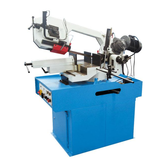
- Page 1 METAL CUTTING BAND SAW MODEL BS-315G Operation Manual...
-
Page 2: Table Of Contents
Table of contents Introduction……………………………………………………………………………………2 1. Accident prevention and safety instruction……………………………………………..3 1.1 Advice for the operator…………………………………………………………………..3 1.2 The electric equipments according to European Standard “2006/42/EC” which some integrating modifications……………………………………………………………..3 1.3 Emergencies according to European Standard “2006/42/EC”………………………4 2. Description of machine…………………………………………………………………...4 2.1 Description of machine and its components ………………………………………….4 2.2 Intended and unsuitable uses of the machine………………………………………...5 3. -
Page 3: Introduction
Introduction This operation instruction manual conforms to the requirements of European Standard 2006/42/EC Machine Directives and subsequent amendments. In the light of this,special attention has been given to safety aspects and accident prevention in the work-place for each stage in the machine’s “life”. Information which could be of particular assistance to the operator has been high lighted. -
Page 4: Accident Prevention And Safety Instruction
1. Accident prevention and safety instruction This machine has been designed to comply with national and community accident-prevention regulations, improper use and / or tampering with the safety devices will relieve the manufacturer of all responsibility. 1.1 Advice for the operator A. -
Page 5: Emergencies According To European Standard "2006/42/Ec
alternating current as low voltage (24V). The equipment is protected against splashes of water and dust. C. Protection of the system against short circuits is ensured by means of rapid fuses and grounding; in the event of a motor overload, protection is provided by a thermal probe. -
Page 6: Intended And Unsuitable Uses Of The Machine
a set of service spanners. 2.2 Intended and unsuitable uses of machine The band sawing machine has been designed and built to cut bars, structural steel and ferrous metal pipes in accordance with the instructions contained in this manual. Therefore, the cutting of other materials is not permitted: if the above recommendations are not observed,the machine could be damaged and the health and safety of the operator put at risk. -
Page 7: Machine Installation
All handing and transportation operations should be carried out by trained staff. 5. Machine installation 5.1 Machine check The machine should be checked to make sure that it has not been damaged during transportation and handing. If the machine appears to have been damaged, contact us immediately. -
Page 8: Cutting Coolant
Make sure that the power supply voltage corresponds to the voltage on the motor plate. Connect the cable to the power supply line observing the color codes of the individual wires, pay particular attention to the earth wire. Connect the machine, make sure that the rotation of circular blade is in the direction shown by the arrow on the guard. -
Page 9: Special Safety Checks
“ ” position. Turn the speed switch to “1” position or Change selector switch to “2” position you like, take hold of #7 handle located at the end of head lever and press the button. The blade will now start turning, position the blade carefully on the piece to be cut. -
Page 10: Maintenance And Repairs
C. Standard work clothing should be used and kept closed and should not have flapping parts. D. The machine should not be cleaned with liquids under pressure. E. In the event of fire, extinguishers should not be used unless they are the powder type. - Page 11 tank with the amount and liquid stated earlier. C. Checking of bench lever functioning Check rotation release-locking lever is working properly regularly. In the event of the lever not locking correctly, loosen #55 grub screw, tighten #56 nut and fasten #55 grub screw again.
-
Page 12: Parts List
Hexagon screw M10X20 Operating panel Adjusting handle Nut M6X16 M12X100 Axis BS315G-0010 Mat 6 Antenna BS315G-0011 Electrical bracket BS-315G-0031 clamp connecting seat Mat 8 BS315G-0009 Lower clamp Bolt M8X20 BS315G-0012 clamp fixed board 1 Roller BS315G-0025 Clamp fixed board 2... - Page 13 ITEM DESCRIPTION QTY ITEM DESCRIPTION Cover board Hexagon screw M8X16 BS315G-0018 Hexagon screw M10X25 Handle switch Mat 5 Pressure handle Under pan BS315G-0015 Hexagon screw M10X12 Nut M10 Moving seat Hexagon bolt M10X45 Driven wheel BS315G-0033 Hexagon screw M10X45 Bearing 6207-2Z Preventing board Sheath Leg BS315G-0016...
- Page 14 ITEM DESCRIPTION QTY ITEM DESCRIPTION Block washer 40 Bearing cover BS315G-0035 Bearing 6208-2Z Bearing 32009X2 Sheath BS315G-0034 Cooling water separation block 108A Hexagon screw M4X25 Rotary shaft BS315G-0036 Cylinder Hexagon screw M10X25 Hexagon screw M12X45 Cylinder bracket BS315G-0023 Hexagon M12X25 Pressure pad Pressure spring Ⅱ...
-
Page 15: Parts Drawing
9. Part drawing... -
Page 17: Electric Drawing
10. Electric drawing... - Page 18 Note: This manual is only for your reference. Owning to the continuous improvement, changes may be made at any time with no obligation on the part of machine. And please note the local voltage for operating machine...
Need help?
Do you have a question about the BS-315G and is the answer not in the manual?
Questions and answers