Table of Contents
Advertisement
Advertisement
Table of Contents

Summary of Contents for SD-MDVR SW-0001A
- Page 1 User manual 4ch Million Pixels SD Mobile DVR USER MANUAL Version 3.0...
-
Page 2: Table Of Contents
User manual CATALOGUE 1 Parts list ............................... 4 2 Product introduction ............................ 4 2.1 Product features ..........................4 2.2 Main Functions ..........................6 2.3 Parameter Sheet ..........................7 2.4 Front Panel ............................ - Page 3 User manual 4.7.2 Speed Alarm ........................29 4.7.3 Acceleration ........................30 4.7.4 Motion Detection ........................ 30 4.7.5 Voltage Alarm ........................31 4.7.6 Serial Port Set ........................32 4.7.7 PTZ ............................. 32 4.8.
-
Page 4: Parts List
User manual 1 Parts list Quantit Device Type Name Unit Basic Basic+GPS/BD Basic+Gps/BD+3/4G MDVR ✔ ✔ ✔ Remote Control ✔ ✔ ✔ Power input wire 1 ✔ ✔ ✔ AV input wire ✔ ✔ ✔ AV output wire ✔ ✔ ✔... - Page 5 User manual Special File System Technology,Solving repeatedly wipe cause file fragmentation, solving SD card file system collapse, data loss and cannot find SD card and file garbled, ensure the integrity of the data. 8-33V Adaptive Wide Voltage input, Super Low Power Consumption Design; SD card storage (maximum support two pieces 128GB SD card.
-
Page 6: Main Functions
User manual Main Functions Main Sub‐Item Instructions Video Channel 4Channel video + 4Channel Audio recording synchronously; Support 4*720P(1280*720),4*D1(704*576),4*HD1(704*288), 4*CIF(352*288) ; Resolution Each channel is individually adjustable. Image Quality 0‐7 levels, 0 is the highest level. OSD Overlays information such as date time and vehicle ID Recording Sub‐System Loop Rec Support SD card loop recording, loop cover previous video Record Mode Timed recording, alarm trigger recording and manual recording Support 1 channel and 4 channels preview. Support enlarge Preview video image when alarm trigger and video rear view trigger; Disk Space pre‐allocated Support disks overwritten function. overwritten Video Search Search video files anytime per day, type(n/a) Support 1 to 4 channels playback. Playback System Playback Support forward and backward play at the speed of: x2 ,x4,x8,x16. Support alarm spot search and time search. Graphical User GUI Setup system parameters with the remote control. Interface 8 channels electrical level alarm input for optional Input... -
Page 7: Parameter Sheet
User manual Parameter Sheet Item Parameter Linux Language Chinese/English/Others (can be customized) Video Compression H.264 Compression Mode OSD Overlays information such as date time and vehicle ID Graphical User Can connect to external LED screen. Setup system parameters with the remote GUI Interface control. 4CH 720P AHD/ 4CH standard definition /2CH high definition+2CH standard Video Input definition mixed video input ,aviation plug Video Output 1CH CVBS+ VGA output for optional, 1.0Vp‐p, 75Ω, aviation plug Support 1 channel and 4 channels preview.,Support Manual/Alarm Trigger full Preview screen preview Resolution 720P/D1/HD1/CIF, MAX:4 channels of 720P Video Quality 0‐7 levels, 0 is the highest level, 7 is the lowest level. PAL: 100f/s , CCIR625 line,50field; NTSC: 120f/s, CCIR525 line,60field; CIF: 256Kbps ~ 1.5Mbps, 8 level video quality optional; Video Standard HD1: 600Kbps ~ 2.5Mbps, 8 level video quality optional; D1: 800Kbps ~ 3Mbps, 8 level video quality optional; 720P: 4Mbps‐6Mbps, 8 levels video quality optional The default setting is auto recording after power on. Timed recording, alarm Record Mode trigger recording and manual recording are supported. - Page 8 User manual 2pieces SD Card,each max 128GB SD Card, mirror recording to protect data from Storage loss Support USB flash disk updating,SD card upgrade , OTA remote upgrade Upgrade automatically Video File Format H.264 General video format Storage File System Special FAT32 File System Front panel supports USB port, support USB flash disk upgrade to backup; hard USB disk box USB port, can back up video data Video Search Search video by Record Time/Record Type etc Video Max support 4CH Replay /Stop/Fast Forward/Fast Reverse at same time Playback Playback Support x 2,x4,x8,x16. fast forward or fast backward play Safety Management User/Admin 2 Levels Different Passwords , support screen lock TTS Voice Support the TTS Voice Broadcast function Broadcast Extension Functions Serial Port Support kinds of Access Equipment such as LED Advertising, PTZ control, Oil Fuel Extension Sensor,etc. Adaptive wide power input, support Wide Voltage, Over‐load、Over‐voltage、 Power Management Short Circuit、Reverse Protection..Support Time Setting/Delay power off Voltage Input DC:+8V ~ +33V...
-
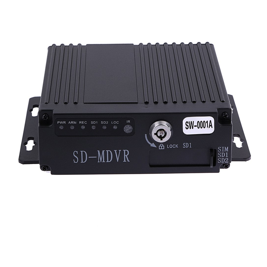
Page 9: Front Panel
User manual Front Panel ① ② ③ ⑤ ④ Front Panel items introduction Silk Item Name Functional Specification screen Power Indicator LED, LED on means powered has connected. Alarm Indicator LED, LED on means alarm event is happening. Video Recording Indicator LED.LED means In the recording SD card 1 Indicator LED, LED ON—Card exists but not recording, LED ○ FLASH—Card 1is recording, LED OFF—Card does not exist Indicators SD card 1 Indicator LED, LED ON—Card exists but not recording, LED FLASH—Card 2 is recording, LED OFF—Card does not exist SD Lock Indicator LED, LED ON—SD Lock is open. IR Remote ○ Infrared remote control receiving hole Receiver It’s used for unload hard disk. ○ Device will power off automatically if power on when HDD lock is SD Lock LOCK open. -
Page 10: 4Ch Mdvr Back Panel
User manual 4CH MDVR Back Panel ① ② ③ ⑦ ⑤ ⑥ ④ 4CH MDVR Back Panel items introduction : Item Name Silk screen Functional Specification Video&Audio ○ 1‐4Channels, with DC 12V output, AV1-AV4 Input interface Video&Audio ○ Video&Audio output interface, with DC 12V output AV OUT Output interface ○ 3G Antenna Port With alarm input&output、 serial port etc.A more detailed ○ SENSOR definition see chapter 1.6.4 ○ USB Interface It’s used to import or export data or upgrade Input Voltage DC 8‐33V,... -
Page 11: 8Ch Mdvr Back Panel
User manual 8CH MDVR Back Panel ① ② ③ ⑦ ⑤ ⑥ ④ 8CH MDVR Back Panel items introduction : Item Name Silk screen Functional Specification 1,2 Channel Video&Audio Input interface, with DC 12V AV1-2 output Video&Audio ○ AV3-4 3,4 Channel Video&Audio Input interface Input interface AV5-6 5,6 Channel Video&Audio Input interface AV7-8... -
Page 12: Power Input Interface Pin Description
User manual 4 Pin aviation 6 Pin aviation plug plug FUNCTION FUNCTION +12V +12V Video Input Audio Input/output Audio Input Video Input/output Video Input Audio Input 2.6.2 Power Input interface pin description Pin Configurations FUNCTION Power- Power+ 2.6.3 I/O Interface Definition I/O Port pin configurations PIN DESCRIPTION FUNCTION... -
Page 13: Remote Controller
User manual Remote Controller Power and Standby Button,Reserved To endter system setting 【 - 】 : 0 9 Key In the setting mode,0-9 is uses to selecet the 【 - 】 number of menu items.In playback mode,the keys to select Number Key single channel playback. -
Page 14: Device Installation
User manual 3 Device Installation Power Cable Connection This MDVR use DC power supply, Wide operating range8 to 33V ★... -
Page 15: Operation Interface Setup
User manual 5. The power cables must can stand beyond 60W.(For example, when the output voltage of car is 12V,the power cables must can bear 5A or more). 6. Please put the cover on the cables, the cover must be wear-resistant, heat-resistant, water-proof, grease-proof, in case of short circuit and open circuit. -
Page 16: Search
User manual Search Query menu includes: Record, Log and Picture, ... -
Page 17: Video Search
User manual 4.1.1 Video Search **** Green color display indicates current day and time exist video file **** “Search Date”: Press the number key to enter date, default is current date. “Start Time”: Press the number key to enter date, default is 00:00. “End Time”: Press the number key to enter date, default is 23:59. -
Page 18: Log Query
User manual 4.1.2 Log Query This menu is to query device operation and working log , you can choose the same type log via log categories. When select a single log, press the keys to quickly flip over, and press to turn to first page or last page. -
Page 19: Terminal Setup
User manual 4.4.1 Terminal Setup By remote control input settings: device number, phone number, license plate number, the provincial domain ID, the City ID, terminal type, manufacturer ID, terminal ID, the device management (data in accordance with the Department of standards, Chinese input can use the soft keyboard input) ... -
Page 20: User Management
User manual 4.4.2 User Management “Password Enable”: You can enable or disable password authentication to access the menu. Modify or setup password of users and the administrator by remote control. **** ADMIN Pass : 111111, USER Pass : 000000 **** 4.4.3 Time Set This menu is to setup device parameters, such as date and time, etc. -
Page 21: Parameters Management
User manual “Power mode”:press the number keys to select the type, the default is ignition mode. “Delay Off”: Press the number keys to enter the time, the default is 5 minutes, can be set to 1440 minutes “Screen time”: Press the number keys to enter the time, the default is 60 minutes, can be set to 0-1440 minutes “Power On”: Press the number key to enter time, setup the timer start time “Power Off”: Press the number key to enter time, setup the timer off time... -
Page 22: Format
User manual 4.4.6 FORMAT Format Disk choice, device will reboot disk after confirming, log and pictures and other related info will be reserved. Attention: Device will format automatically when it starts, new SD card, can be formatted on the computer, in general, it doesn’t need format disk in DVR by manual. -
Page 23: Main Stream
User manual “Video Type”: PAL / NTSC, press [OK] key to select. “Record Mode”: Auto / timer / alarm recording, press [OK] key to select. “Camera Type “: Can switch the status of standard definition , high definition or mixed camera input. “Resolution”:Set the resolution of VGA output. -
Page 24: Sub-Stream
User manual “Enable”: open or close the channel of pre-recording function, press [OK] key to select. “Resolution”: CIF, HD1, D1 and 720P resolution for choosing, press [OK] key to select. “FPS”: 1-25 frame (P standard), 1-30 frame (N standard) channel recording frame rate for choosing. “Image quality”... -
Page 25: Storage Management
User manual Move the cursor to “Timing Recording” and press [OK] button to set up the following timing list. **************************************************************************************** Timer recording start time is before the end time. **************************************************************************************** 4.5.5 Storage management “pre-recorded”: pre-recorded alarm recording time of 0-60 seconds to setup, press number keys to setup. “Alarm delay”: alarm delay recording time, 120-3600 seconds to set up, press number keys to setup. -
Page 26: Center Setup
User manual 4.6.1 Center Setup Set Server IP and Port ; “Monitoring Center”:Set 3G /4G Video Center IP or domain,port information etc, “Network Type”:Set 3G network type, IP address/Domain optional; “Center IP”:3G Server IP/Domain setup. Press right key to enter keyboard interface,input the numbers via remote controller,then press [OK] for setting,;... -
Page 27: Local Network Setup
User manual 4.6.2 Local Network Setup Device Local Network setup “IP”\”Mask”\”Gateway”\ “DNS1” \”DNS2”\”MAC”:IP,Mask,Gateway,MAC setting for LAN network testing. Attention: When net cable directly connect to the device, only can use 4PIN definition net cable (please see more definition in the addenda), otherwise it will lead device dead. 4.6.3 3/4G Setup 3G/4G Network Configuration ... -
Page 28: Wifi Setup
User manual 4.6.4 WIFI Setup “WIFI-EN”:WIFI On/Off Setting,Press [OK] for choosing; “Encr-EN”: WIFI encryption ON/Off Setting,press [OK] for choosing; “Au-Mode”: WIFI Authentication mode setting,Please choose same one with your router, “Enc-Type”: WIFI Encryption type setting,Please choose the one same with your router, “IP”\”Mask”\”Gateway”:WIFI IP/Mask/Gateway setting “SSID”: Input Your WIFI SSID, “PWD”: Same with your WIFI password,... -
Page 29: Io Alarm
User manual 4.7.1 IO Alarm Each channel alarm enable/level/time delay/Linkage information setting; “Enable”:Alarm Trigger enable on/off and alarm type, press [OK] for changing; “Level”:Choose Alarm trigger level,High/Low Level optional,press [OK] for optional; “ Delay”:When alarm trigger,if need delay alarm trigger,time can be set to reduce error alarm, press [OK] for changing;... -
Page 30: Acceleration
User manual “ Speed Source”: The method to get speed, GPS/Pulse Signal Optional, Press [OK] for changing; “ Pulse Number”:Must set Pulse factor for the standard if using Pulse to get car speed information,press Numbers for changing,can search vehicle data or constant speed by several times setting for a certain number “... -
Page 31: Voltage Alarm
User manual “Threshold “: Main is area alarm percentage, generally set 1 or 2, representing 1% or 2% area change images move,it will trigger motion detection alarm. “Sensitivity”: 0-7 levels, 0 is the highest level, 7 is the lowest level. Generally suggest to set 1, the bigger number you choose ,the lower the sensitivity will be, then it’s not easy to alarm as well. -
Page 32: Serial Port Set
User manual 4.7.6 Serial Port Set External Device parameter setting, can connect LED Advertisement/TTS/Oil/Sensor/POS etc ; “ Peripheral”:The external device type option,press [OK] For Changing; “ Baud Rate”:Choose Baud Rate of external device,press [OK] for changing; “ Data Bit”: Choose the Data bit of external device, press [OK] for changing; “... -
Page 33: System Info
User manual 4.8. System Info System Info have 2 parts for detail information;can view by menu or Press INFO. 5 FAQ 5.1. Common problem Q:When Device issue appear,you are confused on how to solve it. A:Check Device Item No & Firmware Version,sent back to us with detail description of issue.Our Technical Team will handle it. -
Page 34: Gps Related Faq
User manual Q:Video Output Lost A:1.Check situation of DVR:Device Input Power;Power Cable Connection;GND Connect to battery;fuse;RED & Yellow Cable of Power must connect together; 2.Check the Screen Power or Check if the Screen change to related AV Channel; 3.Check the connection of Video Output & Screen Cable; Q:Device keep Rebooting A:1)Check working power,if low power device will keep rebooting;... -
Page 35: Client Software Faq
User manual A:1)Choose inside wireless module WCDMA,EVDO,TD-SCDMA, relative module setting is different then SIM Card is different, please make sure the module is corresponding with the SIM Card. 2)If Server IP & Port set correct,if 3G signal strong for dialing;3G dialing successfully or not; 3)Check 3G Antenna connection,dialing will be failed if 3G signal too weak;... - Page 36 User manual 3.If the camera takes an electricity power from the equipment directly, may be the equipment’s electric voltage isn't enough to make camera work as usual; d) The cable that links this channel has problem Q: Can’t playback files on PC successfully? Possible reason is as follows: 1.Have never chosen a record file or document path;...
Need help?
Do you have a question about the SW-0001A and is the answer not in the manual?
Questions and answers
ive got no cameras showing any pics and the log in is all in Chinese and had clicked to English but doesn't change i can use the control to work the screen ok i just have 4 blank cams and in chinese
To change the language from Chinese to English on the SD-MDVR SW-0001A, go to the system settings and select the language option. Choose "English" from the available options.
To resolve the issue of blank camera feeds, check if the camera type and DVR setting mode (AHD HD/Analog/Mixture) match. If they do not match, the system will display "video lost." In Mixture mode:
- Channels 1 and 2 are for AHD high-definition input.
- Channels 3 and 4 are for analog standard-definition input.
Ensure the correct settings are configured to match the connected cameras.
This answer is automatically generated