Table of Contents
Advertisement
Advertisement
Table of Contents

Subscribe to Our Youtube Channel
Summary of Contents for AMB i.t. AMBrc
- Page 1 MANUAL MANUAL MANUAL MANUAL AMBrc system AMBrc system AMBrc system AMBrc system...
-
Page 2: Table Of Contents
Contents Page INTRODUCTION..........................2 INSTALLATION OF THE DETECTION LOOP................4 INSTALLATION OF THE AMBRC DECODER ................10 INSTALLATION OF THE DIRECT POWERED TRANSPONDER..........12 INSTALLATION OF THE RECHARGEABLE TRANSPONDER..........13 CHARGING THE TRANSPONDER....................14 OPERATING THE SYSTEM / TROUBLE SHOOTING ..............15 TECHNICAL SPECIFICATIONS...................... - Page 3 AMB i.t. B.V. Installation Manual AMBrc - Rev. 1.1b...
-
Page 4: Introduction
The AMBrc system is specially designed to time and score RC model car races. The signal sent by an AMBrc transponder mounted on each RC model car is picked up by the detection loop, which is installed in the track. This detection loop is connected to the AMBrc decoder, via a coax cable. -
Page 5: Installation Of The Detection Loop
The carpet can be covered with sand. 6. The detection loop is sensitive to interference, possibly emitted by nearby cables. To avoid possible interference keep all cables 3 m / 10 ft or more away. AMB i.t. B.V. Installation Manual AMBrc - Rev. 1.1b... - Page 6 (excess loop wire must be cut). 8. As the reach of AMBrc loop can be up to 90 cm / 3", especially when the noise (interference) level is low, transponders on other parts of the track should not be able to get closer to the loop than 90cm / 3".
- Page 7 AMB i.t. B.V. Installation Manual AMBrc - Rev. 1.1b...
- Page 8 To prevent this from occurring it is advisable to keep the bridge as short (less than 3 m / 10 ft) and low as possible (less than 45 cm / 1.5 ft). AMB i.t. B.V. Installation Manual AMBrc - Rev. 1.1b...
- Page 9 (part numbers 6704 and 6001/6002/6003) the two loops are connected to the AMBrc decoder. Using two loops will result in a weaker signal for the connected decoder. If very high noise (interference) levels occur, as may happen at night, the speed or split-time loop may have to be disconnected.
- Page 10 (AMB) software. The speed-trap mode is indicated on the AMBrc decoder by rapid flashing of the green LED on the front panel. In speeds trap mode the decoder detects the same transponder again after 0.2 seconds instead of the standard 2 seconds.
-
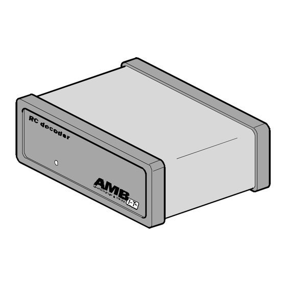
Page 11: Installation Of The Ambrc Decoder
30 cm / 1 ft away from other cables to avoid interference. 2. Connect the RS232 cable between the AMBrc decoder and the RS232 port of the computer (a straight pin to pin RS232 connection cable is needed, such as AMB part number 6201). - Page 12 Maximum allowed current through the transistor is 10mA. The AMBrc decoder is equipped with a USB interface which is for future use, but it can currently be used to get power from a connected (laptop) computer. In that case you may also use the 12VDC power input for backup power.
-
Page 13: Installation Of The Direct Powered Transponder
Whenever power is applied to the radio receiver, the direct powered transponder will show a green LED on both sides. These green LEDS indicate that the direct powered transponder is working. Make sure the transponder can not get detached during a race. AMB i.t. B.V. Installation Manual AMBrc - Rev. 1.1b... -
Page 14: Installation Of The Rechargeable Transponder
For OFF-ROAD RC model cars, the transponder may be fixed underneath the rear wing of the RC model car. When the pin has been forcefully removed from the transponder, the transponder cover can be replaced (part number 00551102). AMB i.t. B.V. Installation Manual AMBrc - Rev. 1.1b... -
Page 15: Charging The Transponder
Warning: Airline regulations demand all electronics to be switched-off when on board aircraft. The AMBrc transponders switch themselves off when the Nimh cells are empty. When airline travel is expected after a race event, do not charge longer than necessary to proceed with the races. -
Page 16: Operating The System / Trouble Shooting
Hits The number of hits, as shown by AMBrc software, is an indication of the number of repeated contacts during a passing. The number of hits varies with the speed of a passing transponder. Transponders should not get closer than 2.5cm / 1” to avoid interfering on each other signals, resulting in low hits. - Page 17 2. Decoder and transponder type and their serial numbers. 3. Worst noise level and minimum indicated transponder signal strength. 4. Use of in-track or bridge detection loop. To contact AMB: please see address chapter 9. AMB i.t. B.V. Installation Manual AMBrc - Rev. 1.1b...
-
Page 18: Technical Specifications
: 3x opto coupled 4-12 VDC / 5-15 mA Aux. Outputs : 2x opto coupled, max 10mA Compatible with the following AMB transponder types : AMBrc (rechargeable type), AMBrc direct power USB connection : not implemented yet, but power can be applied. AMBrc Rechargeable Transponder Dimensions : 35x31x12 mm / approx. -
Page 19: Ec And Fcc Regulations
College Park, GA 30349 The Netherlands U.S.A. Tel: ++31 23 529 1893 Tel. 770-997-8882 / 877-426-2488 Fax: ++31 23 529 0156 Fax. 770-997-0699 Homepage: www.amb.nl Homepage: www.amb-us.com E-mail: support@amb.nl E-mail: support@amb-us.com AMB i.t. B.V. Installation Manual AMBrc - Rev. 1.1b... -
Page 20: Declaration Of Conformity
Herenweg 29a, 2105 MB Heemstede Address, City The Netherlands Country +31 23 529 18 93 Phone number +31 23 529 51 82 Fax number Drawn up in Heemstede, The Netherlands Date June 21, 2000 AMB i.t. B.V. Installation Manual AMBrc - Rev. 1.1b... - Page 21 (See copy of ISO 9001 certification attached) End product quality control is assessed on accordance with AMB i.t. Holding B.V. product quality control procedures, as described and contained in document entitled AMBRC System Quality Assurance, issue 21-06-2000, version 01 Full operational test according to customer specifications...
-
Page 22: Amb I.t. B.v. Installation Manual Ambrc - Rev. 1.1B
Name and function Harry van Dooren, General Manager AMB i.t. B.V. Installation Manual AMBrc - Rev. 1.1b...
Need help?
Do you have a question about the AMBrc and is the answer not in the manual?
Questions and answers