
Summary of Contents for Denford PCB Engraver
- Page 1 PCB Engraver CNC Machine User’s Manual approved http://www.denford.co.uk PCB Engraver Operator Manual Page 1...
-
Page 2: 1: Contact Information
Telephone: General Enquiries 01484 728000 Fax: 01484 728100 e-mail: For sales enquiries contact, sales@denford.co.uk For machine servicing enquiries contact, service@denford.co.uk For customer services, contact customerservices@denford.co.uk Technical Support: Visit Denford Technical Forum at www.denfordata.com/bb Telephone Denford Customer Services: 01484 728000 e-mail: customerservices@denford.co.uk Monday to Friday 8.30am - 4.30pm GMT... - Page 3 Table of Contents 1 : Notes PCB Engraver Operator Manual Page 3...
-
Page 4: Table Of Contents
10: Specifi cation ..................... 33 10: EC Declaration of Conformity for Machines Prior to 29.12.09......34 10: EC Declaration of Conformity for Machines After 29.12.09 ......35 10: PCB Engraver Noise Level Test Results ............36 11: Glossary......................37 12: Notes ........................ 40... -
Page 5: 1: Warning Notices
fi tted, or any ad just ments are made to the controlling devices without prior notifi cation from Denford Limited. Please refer to the information held in your separate Warranty pack, for specifi c details. - Page 6 If you have any doubts and/or questions regarding the use, spec i fi ca tion, servicing, or features of your machine, please con tact Denford Cus tom er Services. Denford Limited reserves the right to change the spec i fi ca tion and/or operating features regarding this CNC machine without notice or documentation.
-
Page 7: 1: About This Manual
If you have any doubts and/or questions regarding the spec i fi ca tion, servicing, or features of your Engraver, please con tact Denford Cus tom er Services. Denford Limited reserves the right to change the spec i fi ca tion and/or operating features regarding this CNC machine without notice or documentation. -
Page 8: 1: Introducing Your Pcb Engraver
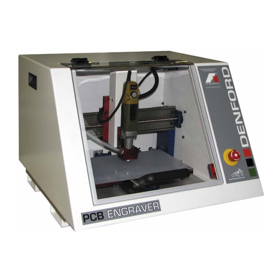
1: Introducing your PCB Engraver Congratulations on your purchase of a PCB Engraver. In this manual you will learn how to setup and use your Machine correctly and safely. Your Engraver is a three axis CNC Engraver with a large work area, allowing machining of materials approaching 330 x 210mm in size. -
Page 9: 1: Before Beginning To Setup
The following equipment is supplied as standard with your Engraver CNC machine : • PCB Engraver CNC machine. Note that the precise specifi cation of your CNC machine will depend on any options selected at the time of ordering (see below). -
Page 10: 2: Safety Features Overview And Precautions
• Visually check door and window for signs of cracks or chips. Any damage should be reported immediately to Denford and a suitable replacement obtained without delay. • Regularly check door hinges for correct tension and adjust or replace if necessary. -
Page 11: 2: Safety Features - Emergency Stop Button
If the machine is powered up with the door open, the axes and spindle will be inhibited until the door is closed and the machine has been homed. PCB Engraver Operator Manual Page 11... -
Page 12: 2: Dust Extraction & General Wood Precautions
The dust extraction system used should be independently tested every 14 months to ensure that dust is kept well below the maximum exposure limits set by law. Denford can supply dust extraction systems for your machine, or you may wish to connect your own system. -
Page 13: 3: Unpacking And Lifting Your Cnc Machine
To obtain better access to the machine, remove all the sides from the delivery box. Your PCB Engraver weighs 43 kg. for bench mounting: with fl oor Caution. Always use sensible standing unit it weighs 157 kg. -
Page 14: 3: Choosing A Site For Your Cnc Machine
Machine depth (front to covered or back) 585mm (23”). blocked. Plan View show ing Ideal Ma chine Computer desk, monitor, Layout and Operating Po si tions. keyboard and mouse angled towards Operator. Machine Operator. PCB Engraver Operator Manual Page 14... -
Page 15: 3: Removing Protective Coatings And Packaging
CNC machine. To avoid the potential risk of ignition / explosion, ensure that any trapped solvent vapours can exit fully from any enclosed areas on the CNC machine. Wait at least 1 hour before attempting to operate the CNC machine. PCB Engraver Operator Manual Page 15... -
Page 16: 4: Switching The Engraver On
4: Switching the Engraver On Follow these instructions to switch on your Engraver: Warning 1) Check the Denford machine link cable is fi tted securely between the USB port socket on the machine controller PC and the USB socket, Do not connect cables located on the right-hand panel of the Engraver cabinet. -
Page 17: 4: Switching The Engraver Off
4: Switching the Engraver Off Follow these instructions to switch off your Denford Engraver off: Warning 1) Wait for the Engraver to fully complete any machining or processing of any operational instructions. Never attempt to access 2) Open the safety guard door and remove any fi nished parts from the electronic hardware the working area. -
Page 18: 4: Homing The Machine Axes (Home Mode)
CNC machine after loading or confi guring any offsets. The machine datum position is set by Denford and can never be moved, since it defi nes the physical movement capability of the CNC machine. PCB Engraver Operator Manual Page 18... -
Page 19: 4: Manual Control - Axis Defi Nitions (Jog Mode)
Minus (-) Z movements run down, towards the fl oor of the machine and positive (+) Z movements run up, away from the fl oor of the machine. Jog Keys to move axis -Page up and Page down PCB Engraver Operator Manual Page 19... -
Page 20: 4: Front Machine Operators Panel
(continuing to cut all power to the machine drives) until the release sequence is performed. To release a closed emergency stop button, push and turn the button clockwise until it springs back out. PCB Engraver Operator Manual Page 20... -
Page 21: 5: Spindle Motor Features And Controls
Spindle Motor On/Off Switch Spindle Motor Speed Control 5000 - 20000 RPM Spindle Motor Clamp Button Tool Collet Spindle Motor Spindle Motor Front View Rear View PCB Engraver Operator Manual Page 21... -
Page 22: 5: Performing A Tooll Change
(the tool profi les allocated to each tool number may be listed at the beginning of your CNC program). Close the safety guard door and clear the software message window to resume your machining. PCB Engraver Operator Manual Page 22... - Page 23 Release tool collet by pressing on the button and turning the spanner supplied. Insert engraving tool and very lightly tighten the collet. Using the tool setting gauge, push the tool into the spindle on the Z=0 setting. Now fully tighten the collet. PCB Engraver Operator Manual Page 23...
- Page 24 Loosen the cap screw and adjust the fl oating ring by turning until the tool tip protrudes… The tool should protrude just enough to break the surface of the engraving material or PCB. Now tighten the cap screw. PCB Engraver Operator Manual Page 24...
- Page 25 Setting up different tools is now simple-just set the tool with the gauge. If you want to use a drilling tool, then use the gauge to set how far the tool will protrude and thus travel into the material. PCB Engraver Operator Manual Page 25...
-
Page 26: 6: Planning Procedure For Maintenance Work
• When maintenance work has been completed, check that the more than one power replaced or serviced parts work correctly, before allowing general supply to the machine. operation of the machine. When isolating machine always ensure that all power sources have been disconnected. PCB Engraver Operator Manual Page 26... -
Page 27: 7: Maintenance Schedule
• Lubricate the slideways and leadscrews - see p29 • Check all exposed screws and nuts for tightness. • Visually check door for signs of cracks or chips. Any damage should be reported immediately to Denford and a suitable replacement obtained without delay. Door Part Number PCB/0401D Every Two Months •... -
Page 28: 7: Cleaning The Engraver Motor
The X axis switch is mounted on the rear removing the the white face of the crossbeam and is located head cover. immediately above the Y axis switch. PCB Engraver Operator Manual Page 28... -
Page 29: 7: Lubrication Of The Slideways And Leadscrews
7: Lubrication of the slideways and leadscrews Use of Swansil Lubricant on Denford Machines 1. Clean down machine with brush and vacuum - do not use compressed air. 2. Position the Machine in mid-travel. 3. Open the guard. 4. Isolate machine from power supply. -
Page 30: 8: Maintenance Log
8: Maintenance Log Date of Name of personnel Details of maintenance carrying out the maintenance work work. maintenance. completed. PCB Engraver Operator Manual Page 30... - Page 31 8: Maintenance Log Date of Name of personnel Details of maintenance carrying out the maintenance work work. maintenance. completed. PCB Engraver Operator Manual Page 31...
-
Page 32: 9: Technical Support
Please refer to the information held in your separate Warranty pack, for specifi c details. Before contacting Denford for support, please read your hardware and software manuals and check the Denford websites for support. Internet (access technical support and FAQ sections): www.denfordata.com/bb... -
Page 33: 10: Specifi Cation
10: Specifi cation of the PCB Engraver Safety Features: • Manual operation, totally enclosed cabinet with safety guard door. • Emergency stop button. • Toolpath graphics to verify part programs prior to machining. Mechanical Details: • Travel X axis 330mm (13”). -
Page 34: 10: Ec Declaration Of Conformity For Machines Prior To 29.12.09
Also the following standards (where applicable) ……………………………… And complies with the relevant health and safety requirements ……………………………… Signature of responsible person ……………………………… Position Senior Design Engineer Signed at Birds Royd Brighouse West Yorkshire HD6 1NB United Kingdom PCB Engraver Operator Manual Page 34... -
Page 35: 10: Ec Declaration Of Conformity For Machines After 29.12.09
HD6 1NB United Kingdom Declares that the machinery described: 1. Make Denford Limited 2. Model PCB Engraver Standard Engraver 3. Serial Number Fulfi ls the relevant provisions of the following Directives Machinery Directive 2006/42/EC Low Voltage Directive (LVD) 2006/95/EC EMC Directive (2004/108/EC). -
Page 36: 10: Pcb Engraver Noise Level Test Results
10 : PCB Engraver Series Noise Level Test Noise Level test Test Report No: NL-PCB-01S Machinery Manufacturer: Denford Limited. Machinery Type/Model: PCB Engraver Equipment: Meter Ref. Standard ST-805 Denford PCB Engraver DP50 Extraction Unit Test Conditions: Spindle speed: 0 - 20000 RPM. -
Page 37: 11: Glossary
Signs are used to indicate the direction of movement. INPUT ......... The transfer of external information (data) into a control system. INTERFACE ....... The medium through which the control/computer directs the machine tool. PCB Engraver Operator Manual Page 37... - Page 38 SLIDES......... The 3 machine axes - see axis. SPINDLE SPEED ....The rate of rotation (velocity) of the machine head / cutting tool, measured in RPM. SOFTWARE ....... Programs, tool lists, sequence of instructions etc... PCB Engraver Operator Manual Page 38...
- Page 39 WORD ........ A combination of a letter address and digits, used in a CNC program (ie, G42, M04 etc.). VIRTUAL REALITY....A fully interactive, three dimensional, computer based simulation of a real world object or event. Z TOOL OFFSET ....See Tool Offset PCB Engraver Operator Manual Page 39...
-
Page 40: 12: Notes
12: Notes Use this page to make a note of any parts of the software you have changed or confi gured, for example, common tooling set-ups, machine parameters, changes to installation paths or passwords etc. PCB Engraver Operator Manual Page 40... - Page 41 2010 If in doubt, please refer to your order and delivery invoices. No liability can be accepted by Denford Limited for loss, damage or injury caused by any errors in, or omissions from, the information supplied in this manual. Denford Limited reserves the right to alter any specifi...
Need help?
Do you have a question about the PCB Engraver and is the answer not in the manual?
Questions and answers