Sign In
Upload
Download
Table of Contents
Contents
Add to my manuals
Delete from my manuals
Share
URL of this page:
HTML Link:
Bookmark this page
Add
Manual will be automatically added to "My Manuals"
Print this page
×
Bookmark added
×
Added to my manuals
Manuals
Brands
Brother Manuals
Sewing Machine
SB3734T
Service manual
Brother SB3734T Service Manual
Hide thumbs
1
2
3
Table Of Contents
4
5
6
7
8
9
10
11
12
13
14
15
16
17
18
19
20
21
22
23
24
25
26
27
28
29
30
31
32
33
34
35
36
37
38
39
40
41
42
43
44
45
46
47
48
49
50
51
52
53
54
55
56
57
58
59
60
61
62
63
64
65
66
67
68
69
70
71
72
73
74
75
76
77
78
79
80
81
82
83
84
85
86
87
page
of
87
Go
/
87
Contents
Table of Contents
Bookmarks
Table of Contents
Table of Contents
1 Outline of Mechanism
Main Mechanisms
Driveline
Main Frame / Covers / Upper Thread Guide
2 Disassembly with Assembling Note
Disconnecting Cables and Removing Accessories
Clothplate Cover Assy
Front Cover Assy
Panel Plate L Assy
Rear Cover Assy
Spool Stand Base Assy
Thread Tension L Assy
Looper Thread Take-Up
Oil Pan
Lamp / Electrical Parts / Main Motor Unit
LED Assy / Motor L Assy
Presser Foot Unit
Presser Foot Adjusting Screw / Presser Foot Holder Assy / Presser Bar
Presser Lifter Shaft Assy
Upper Blade / Lower Blade / Looper
Needle Plate Assy / Stitch Width Dial Assy
Upper Knife Holder
Lower Knife Holder Assy
Over Looper L Assy
Lower Looper / Movable Needle Guard
UL Lever
Upper Knife Plate Assy
Upper Knife Lever / Upper Knife Arm / Feed Adjusting Cam
OL Link Plate / OL Lever
OL Eccentricity / UL Rod / UL Eccentricity
Feed Mechanism
Differential Adjusting Plate
Feed Bar Assy
Feed Rod
Feed Dial
Driving Mechanism
Hand Wheel Assy
Spiral Bevel Gears L / Looper Driving Shaft
Feed Adjusting Lever / Differential Adjusting Lever / Differential Dial Stand Assy
Needle Bar
Needle Bar Driving Lever Assy
3 Adjustment
Presser Bar Height Adjustment
Needle Bar Height Adjustment
Needle Bar Balance Position Adjustment
Lower Looper Position Adjustment
Lower Looper Timing Adjustment
Front / Back Position of Lower Looper Adjustment
Movable Needle Guard Position Adjustment
Fixed Needle Guard Position Adjustment
Over Looper Position Adjustment
Over Looper Timing Adjustment
Over Looper / Lower Looper Gap Adjustment
Feed Dog Height Adjustment (1)
Feed Dog Height Adjustment (2)
Feed Timing Adjustment
Thread Tension Adjustment
Thread Tension Release Adjustment
Stitch Width Dial Adjustment
Lower Knife / Upper Knife Position Adjustment
Motor Position Adjustment
Looper Take-Up Position Adjustment
Thread Take-Up Position Adjustment
Advertisement
Quick Links
1
Main Mechanisms
Download this manual
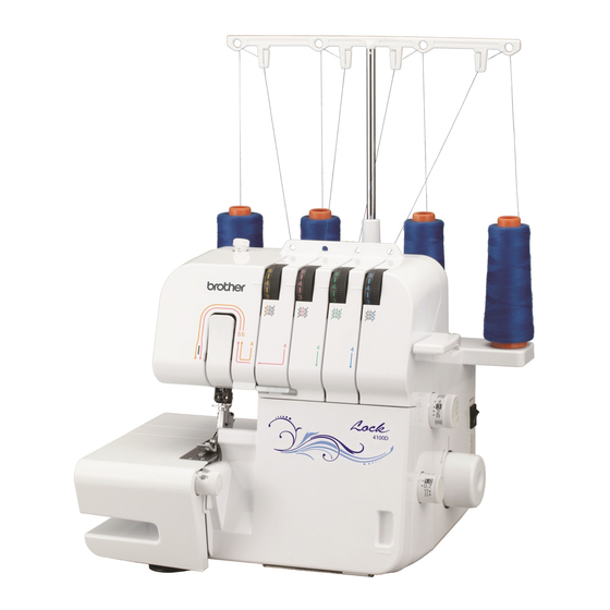
Home Overlock Machine
SERVICE MANUAL
MODEL :
2104D/2104DAV
M343D/4100D/SB3734T
2504D/1034DX
CONFIDENTIAL
2015 Brother Industries, Ltd.
c
All rights reserved.
Published :
Nov.,2015
Revised :
Dec.,2016
Table of
Contents
Previous
Page
Next
Page
1
2
3
4
5
Advertisement
Table of Contents
Need help?
Do you have a question about the SB3734T and is the answer not in the manual?
Ask a question
Questions and answers
Related Manuals for Brother SB3734T
Sewing Machine Brother ST4031HD Operation Manual
Compact overlock machine (76 pages)
Sewing Machine Brother Simplicity SB3129 Manual De Instrucciones
Máquina de coser (156 pages)
Sewing Machine Brother Simplicity SB3129 Operation Manual
Users manual - english (156 pages)
Sewing Machine Brother Simplicity SB530T Operation Manual
Users manual - english and spanish (104 pages)
Sewing Machine Brother SB530T Operation Manual
(104 pages)
Sewing Machine Brother Simplicity SB7050E Quick Setup Manual
Quick setup guide multi - english and spanish (28 pages)
Sewing Machine Brother Simplicity SB7050E Operation Manual
Computerized embroidery machine (96 pages)
Sewing Machine Brother Simplicity SB170 Operation Manual
Users manual - english (92 pages)
Sewing Machine Brother Simplicity SB700T Operation Manual
Computerized sewing machine (72 pages)
Sewing Machine Brother SB7900E Service Manual
Computerized sewing machine (235 pages)
Sewing Machine Brother SB3150 Operation Manual
(144 pages)
Sewing Machine Brother S-7200C Instruction Manual
Single needle direct drive straight lock stitcher with thread trimmer (80 pages)
Sewing Machine Brother Sewing Machine User Manual
Brother sewing machine (17 pages)
Sewing Machine Brother Sewing Machine Quick Reference Manual
Brother sewing machine (32 pages)
Sewing Machine Brother S-7250A Instruction Manual
(88 pages)
Sewing Machine Brother ST371HD Operation Manual
(52 pages)
This manual is also suitable for:
4100d
2104dav
2104d
M343d
1034dx
2504d
Table of Contents
Save PDF
Print
Rename the bookmark
Delete bookmark?
Delete from my manuals?
Login
Sign In
OR
Sign in with Facebook
Sign in with Google
Upload manual
Upload from disk
Upload from URL


Need help?
Do you have a question about the SB3734T and is the answer not in the manual?
Questions and answers