Table of Contents
Advertisement
Instruction Manual
Form 5177
March 1999
4150K and 4160K Series Wizard II Pressure
Controllers and Transmitters
Contents
. . . . . . . . . . . . . . . . . . . . . . . . . . . . . .
. . . . . . . . . . . . . . . . . . . . . . . . . . . . .
. . . . . . . . . . . . . . . . . . . . . . . . . . . . . . . . . .
. . . . . . . . . . . . . . . . . . . . . . . . . . . . . . .
. . . . . . . . . . . . . . . . . . . . . . . . . . . . . . . .
. . . . . . . . . . . . . . . . . . . . . . . . . .
. . . . . . . . . . . . . . . . . . . . . . . . . . . . . .
. . . . . . . . . . . . . . . . . . . . . . . . . . . . . . .
. . . . . . . . . . . . . . . . . . . . . . . . . .
. . . . . . . . . . . . . . . . . . . . . . . . . . . .
. . . . . . . . . . . . . . . . . . . . . . . . . . . .
. . . . . . . . . . . . . . . . . . . . . . . . . . .
. . . . . . . . . . . . . . . . . . . . . . . . . . . . . .
. . . . . . . . . . . . . . . . . . . . . . . . . . . . . . . .
. . . . . . . . . . . . . . . . . . . . . . . . . . . . . .
. . . . . . . . . . . . . . . . . . . . . . .
. . . . . . . . . . . . . . . . . . . . . . . . . . . . . . .
. . . . . . . . . . . . . . . . . . . . . . . . . . .
. . . . . . . . . . . . . . . . . . . . . . . . . . . . . .
. . . . . . . . . . . . . . . . . . . . . . . .
. . . . . . . . . . . . . . . . . . . . .
. . . . . . . . . . . . . . . .
. . . . . . . . . . . . . . . . . . . . . .
. . . . . . . . . . . . . . .
. . . . . . .
. . . . . . . .
. . . . . . . . .
. . . . . . . . . . . . . . . . . . . .
. . . . . . . . . . . . .
. . . . . . . . . . . .
. . . . . . . . . . . .
. .
. . . . . . . . . . . . . . . .
. . . . . . . . . . . . . . . . . . . .
. . . . . . . . . . . . .
. . . . . .
4150K and 4160K Series
2
2
2
2
2
2
2
5
5
5
5
5
6
8
8
8
9
W3525-1 / IL
9
9
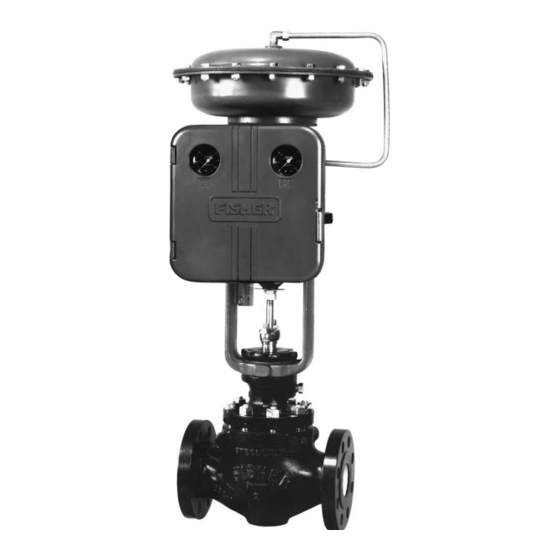
Figure 1. Wizard II Controller Yoke-Mounted
9
on Control Valve Actuator
10
11
11
11
11
. . . . . . . . . . . . . . . . . . . . . . . . . . . . . . .
12
12
12
12
14
14
14
15
15
15
15
. . . . . . . . . . . . . . . . . . . . . . . . . . . . . . .
. . . . . . . . .
. . . . . . . . . . . . . . . . . .
. . . . . . . . . . . . . . . . . . . . . . . . .
. . . . . . . . . . . . . . . . . . . . . . . . .
. . . . . . . . . . . . . . . . . . . .
. . . . . . . . . . . . . . . . . . . . . . .
. . . . . . . . . . . . . . . . . .
. . . . . . . . . . . . . . . .
. . . . . . . . . . .
. . . . . . . . . . .
. . . . . . . . . . . . . . . . . .
16
16
16
16
17
17
18
18
18
18
19
19
20
Advertisement
Table of Contents

Summary of Contents for FISCHER 4150K
-
Page 1: Table Of Contents
Instruction Manual Form 5177 4150K and 4160K Series March 1999 4150K and 4160K Series Wizard II Pressure Controllers and Transmitters Contents Introduction ...... -
Page 2: Introduction
Replacement ......Specifications for the 4150K and 4160K Series con- Relay Disassembly . - Page 3 4150K and 4160K Series Table 1. Specifications Available Configurations Zero Adjustment (Transmitters Only) See table 2 Continuously adjustable to position span of less than 100% anywhere within the sensing element Input Signal range Type: Gauge pressure, vacuum, compound pressure, or...
- Page 4 4150K and 4160K Series Table 2. Available Configurations TYPE NUMBER Bourdon Tube Bellows Sensing Element DESCRIPTION DESCRIPTION Sensing Element Sensing Element Gauge Differential (Gauge Pressure Pressure Pressure Only) Proportional-only controller 4150K 4152K 4154K Without anti-reset windup 4160K 4162K 4164K Proportional plus reset controller...
-
Page 5: Wall Mounting
Wall Mounting neering practices. Refer to figure 3. All pressure connections on 4150K and 4160K Series instruments are 1/4-inch NPT female. Use 1/4-inch (6 Drill four holes in the wall using the dimensions shown mm) or 3/8-inch (10 mm) pipe or tubing for supply and in figure 3. -
Page 6: Process Pressure
4150K and 4160K Series 2 INCH (NOMINAL) PIPE VENT ASSEMBLY (KEY 15) 11/32 (8.7) MOUNTING HOLES FOUR HOLES CUTOUT FOR FOR WALL PANEL MOUNTING MOUNTING NOTES: 1. ALL CONNECTIONS ARE 1/4 INCH NPT FEMALE. HIGH-PRESSURE CONNECTION FOR DIFFERENTIAL- INCH (mm) PRESSURE UNITS. - Page 7 4150K and 4160K Series Table 5. Supply Pressure Requirements MAXIMUM ALLOWABLE SUPPLY OUTPUT OUTPUT NORMAL OPERATING SUPPLY NORMAL OPERATING SUPPLY PRESSURE TO PREVENT INTERNAL PRESSURE TO PREVENT INTERNAL SIGNAL RANGE PRESSURE PART DAMAGE Psig 3 to 15 or 0 and 20 (differential gap)
-
Page 8: Vent Assembly
4150K and 4160K Series PROPORTIONAL BAND ADJUSTMENT KNOB PRESSURE-SETTING KNOB (KEY 36) PRESSURE-SETTING DIAL (KEY 38) CALIBRATION ADJUSTER (KEY 41) FLAPPER (KEY 45) 48B6003-A ADJUSTER SCREWS (KEY 43) NOZZLE (KEY 57) A6038-1 / IL Figure 5. Proportional-Only Controller Adjustment Locations... -
Page 9: Adjustments
4150K and 4160K Series the adjustments and calibration procedures are com- For direct-acting controllers: plete, close and latch the cover. 4. Apply an input pressure equal to the sensing element To better understand the adjustments and overall op- lower range value. -
Page 10: Startup: Proportional-Only Controllers
4150K and 4160K Series IF OUTPUT IS: IF OUTPUT IS: BELOW ABOVE ABOVE BELOW 8 TO 10 PSIG 8 TO 10 PSIG 8 TO 10 PSIG 8 TO 10 PSIG (0.6 TO 0.7 BAR) (0.6 TO 0.7 BAR) (0.6 TO 0.7 BAR) (0.6 TO 0.7 BAR) -
Page 11: Proportional-Plus-Reset Controller
4150K and 4160K Series RESET ADJUSTMENT KNOB PROPORTIONAL BAND ADJUSTMENT KNOB PRESSURE SETTING KNOB (KEY 36) PRESSURE SETTING DIAL (KEY 38) CALIBRATION ADJUSTER (KEY 41) FLAPPER (KEY 45) 48B6002-A ADJUSTER SCREWS (KEY 43) A5433-3 / IL NOZZLE (KEY 57) Figure 8. Proportional-Plus-Reset Controller Adjustment Locations... -
Page 12: Adjustment: Reset
4150K and 4160K Series The proportional band adjustment determines the row on the anti-reset windup assembly (key 186, in amount of change in controlled pressure required to figure 20). Remove the assembly and install the two cause the control valve to stroke fully. It may be ad- O-rings (key 367, not shown), and cover (key 369, not justed from 3–100 percent of the nominal sensing ele-... - Page 13 4150K and 4160K Series 8. Adjust the nozzle (key 57) until the controller output IF OUTPUT IS: pressure is between 8 and 10 psig (0.6 and 0.7 bar). 9. Apply an input pressure equal to the sensing element lower range value.
-
Page 14: Calibration: Anti-Reset Windup
4150K and 4160K Series liquid flow). For a slow process (example: tempera- IF OUTPUT IS: ture), calculate the percentage from the equation be- low: For a slow process, determine the initial proportional band setting in percent from the following equation: Allowable Overshoot P.B. -
Page 15: Adjustments
4150K and 4160K Series 2. Use the calibration procedures for proportional-only controllers. 3. Upon completion of the calibration procedures, re- install the tubing (key 104) in its original location. And, continue with the following procedures. Note After reinstalling the tubing (key 104) in... -
Page 16: Startup: Differential Gap Controllers
4150K and 4160K Series SPAN ADJUSTMENT KNOB ZERO ADJUSTMENT KNOB (KEY 36) PRESSURE SETTING DIAL (KEY 38) ADJUSTER SCREWS (KEY 43) FLAPPER (KEY 45) 48B6004-B CALIBRATION ADJUSTER (KEY 41) NOZZLE (KEY 57) A6039-3 / IL Figure 12. Transmitter Adjustment Locations c. -
Page 17: Adjustment: Span
4150K and 4160K Series dial. Rotate the pointer clockwise to increase or coun- Depending upon the transmitter action, perform one or terclockwise to decrease the output depending on the other of the following procedures. transmitter action and desired setting. For direct-acting transmitters: For direct-acting transmitters, zero adjustment deter- 4. -
Page 18: Startup: Transmitters
4150K and 4160K Series pansion or contraction of the bellows or differential IF OUTPUT IS: bellows. Proportional-Only Controllers As shown in figure 14, supply pressure enters the relay and bleeds through the fixed orifice before es- BELOW ABOVE 15 PSIG 15 PSIG caping through the nozzle. -
Page 19: Controllers With Anti-Reset Windup
4150K and 4160K Series INLET END OF CONSTANT SUPPLY PRESSURE RELAY VALVE SMALL DIAPHRAGM LARGE DIAPHRAGM EXHAUST FIXED ORIFICE EXHAUST END OF RELAY VALVE PROPORTIONAL BELLOWS PIVOTING CROSS SPRINGS BOURDON TUBE FIXED PIVOT NOZZLE BEAM AND RESET FLAPPER VALVE RESET BELLOWS... -
Page 20: Transmitters
If the installation includes a 67 Series filter regulator, periodically open the drain on the filter regulator to Three gauge configurations are available for 4150K drain accumulated moisture. Also, push the cleaner and 4160K units. wire on the relay orifice (key 88, figure 23). Check the... -
Page 21: Replacing Bourdon Tube
4150K and 4160K Series pressure connection (key 107) for a process pressure 3. Disconnect the control tubing (key 132). Unscrew gauge. If a supply pressure gauge is required, a gauge two screws (key 77) and washers (key 76), and re- with a 1/4-inch connecting stem (key 14) must be move the Bourdon tube (key 62). -
Page 22: Changing Proportional Or Reset Valve
4150K and 4160K Series 5. Disconnect the link (key 71M) and bearing (key 3. Refer to figure 20. Install the replacement relief 71L) from the beam. Be careful to avoid losing the valve with the arrow positioned so that the controller bearing. - Page 23 4150K and 4160K Series PROPORTIONAL TUBING PROPORTIONAL (KEY 104) TUBING (KEY 104) RELAY TUBING (KEY 103) REVERSING BLOCK (KEY 59) REVERSE BELLOWS POSITION DIRECT (KEY 52) ACTING REVERSE POSITION ACTING POSITION BEAM (KEY 44) REVERSING BLOCK (KEY 59) PROPORTIONAL RESET VALVE...
-
Page 24: Relay Repair
4150K and 4160K Series PROPORTIONAL TUBING (KEY 104) RELAY TUBING (KEY 103) REVERSE REVERSING POSITION BLOCK (KEY 59) REVERSE ACTING DIRECT POSITION ACTING POSITION REVERSING BLOCK BEAM (KEY 44) (KEY 59) NOTES: P = POPORTIONAL BELLOWS X = NO PRESSURE B2671 / IL Figure 16. -
Page 25: Relay Assembly
4150K and 4160K Series 3. Remove the casing screws (key 96), casing as- 9. Install the relay as described in steps 7 and 8 in the sembly (key 85), and top diaphragm (key 91). On a relay replacement section. high-temperature relay, also remove the top gasket (key 100) that covers the top diaphragm. -
Page 26: Parts Ordering
22B0462 X022 Common Parts (Figures 19 through 22) Parts Ordering Case Ass’y, aluminum For all 4150K and 4160K Series, std or 2 psi Whenever corresponding with the sales office or sales (0.14 bar) pressure tested case & cover 47B9513 X012 representative about this equipment, mention the seri- Cover, Ass’y aluminum... - Page 27 (KEY NOS. SHOWN IN FIGURE 21 OR 22) 48B6004-B / DOC NOTE: KEYS 10, 81, 105 AND 108 ARE NOT SHOWN Figure 19. Typical Direct-Acting 4150K Series Assembly B2651-1 / IL Description Part Number Description Part Number Control Pressure Block...
- Page 28 ADJUSTMENT SUBASSEMBLY (KEY NOS. SHOWN IN FIGURE 20 OR 21) NOTE: KEYS: 10, 81, 105 NOT SHOWN 48B6003-A B2652 / IL Figure 19.Typical Direct-Acting 4150K Series Assembly (Continued) Description Part Number Description Part Number Dial, aluminum Dial, aluminum For Bourdon tube controllers (con’t) For Bourdon tube controllers (con’t)
- Page 29 4150K and 4160K Series RESET RESTRICTION PILOT RELAY VALVE ASSEMBLY PROPORTIONAL BAND ADJUSTMENT SUBASSEMBLY (KEY NOS. SHOWN IN FIGURE 20 OR 21) NOTE: KEYS: 10, 81, 105, 115 NOT SHOWN 48B6002-A Figure 20. Typical Direct-Acting 4160K Series Assembly B2653-1 / IL...
- Page 30 4150K and 4160K Series NOTES: ARROW DOWN—RELIEVES ON DECREASING OUTPUT (OUTPUT @ SUPPLY DURING SHUTDOWN) ARROW UP—RELIEVES ON INCREASING OUTPUT (OUTPUT @ ZERO DURING SHUTDOWN) KEY 21 IS NOT SHOWN. 48B6001-B / DOC Figure 20. Typical Direct-Acting 4160K Series Assembly (Continued)
- Page 31 0–10 psig (0–0.7 bar) positive 1K4934 27022 Compensator Tubing Assembly, sst 0–15 psig (0–1.0 bar) positive, Types 4150K, 50KS, 52K, 52KS, 0–30 inches Hg (0–1.0 bar) vacuum, 54K, 55K, 57K, & 58K 1H6864 000A2 15–0–7.5 psig (500–0–500 mbar) compound 1H4483 27022 Types 4160K, 60KF, 62K, 62KF &...
- Page 32 4150K and 4160K Series SHOWN WITH TRANSMITTER DIAL & SCREW, KEY 38 & 79 SCREW (KEY 71K) LINK (KEY 71M) LINK (KEY 71M) SCREW (KEY 71K) BEARING BEARING (KEY 71L) (KEY 71L) 26A7675-B / DOC 26A7683-B / DOC NOTES: 26A7681-A /DOC...
-
Page 33: Relay Assembly
4150K and 4160K Series Description Part Number Description Part Number Control Tubing Assembly (cont’d) Machine Screw, steel pl (4 req’d) 1A8664 X00A2 For differential-pressure Bottom Gasket, silicone bellows instruments, sst 1H4526 000A2 High Temp construction only 1K7001 04142 Control Tubing Assembly, sst... - Page 34 4150K and 4160K Series APPLY LUB 22B0463-C / DOC APPLY LUB 22B0462-C / DOC Figure 23. Relay Assemblies Description Part Number Description Part Number Spacer Spool, steel (specify quantity req’d) Cap Screw, steel pl (not shown) (specify quantity req’d) Types 470, 472, 480, 513, 656, 657, 667, Type 115 pipe stand 1051, 1052 &...
- Page 35 4150K and 4160K Series Description Part Number Description Part Number Cap Screw, steel pl (not shown) Pipe Nipple, pl galvanized steel (not shown) Types 126 & 127 1C5958 24052 For mounting on Types 470, 472, 480, 513, 656, Pipe Nipple, steel (not shown) (specify quantity req’d) 657, panel, pipe stand, 1051, 1052 &...
- Page 36 4150K and 4160K Series subassembly, they are also included with the bellows assembly, key 71; jam nut, key 72; washer, key 73; assembly, key 71. When ordering the subassembly as spring seat, key 74; machine screw, key 75, quantity indicated by the table below, one of each of the follow- of 4;...
Need help?
Do you have a question about the 4150K and is the answer not in the manual?
Questions and answers