Table of Contents
Advertisement
Quick Links
- 1 Articulator Manipulations
- 2 The Denar Mark II Articulator (Semi-Adjustable)
- 3 Articulator Adjustments
- 4 The Immediate and Progressive Side Shift Adjustments (Bennett Shift)
- 5 Locating Three Reference Points on Patient's Face
- 6 The Denar Mark II Facebow/Earbow (Model D31Ab)
- 7 Mounting the Casts in the Articulator
- Download this manual
Advertisement
Table of Contents

Summary of Contents for Denar Mark II
- Page 1 The Dénar ® Mark II System TECHNIQUE MANUAL...
- Page 3 The Dénar ® Mark II System TECHNIQUE MANUAL Published by Whip Mix Corporation - West 1730 East Prospect Rd., Suite 101 Fort Collins, CO 80525 Toll-Free: 1-800-201-7286 Fax: 1-970-472-1793 www.whipmix.com...
- Page 4 Celenza for their contributions in the early design phases of the instrumentation system. In planning the preparation of the Mark II Technique Manual, it was our intent that it encompass more than just mechanical instruction in the use of the Denar ®...
-
Page 5: Table Of Contents
Introduction Who Should Use The Mark II System ......5 Why Should The Mark II System Be Used ......6 The Denar ®... -
Page 6: Lockscrew
Also the microadjustable adjustment lockscrews illustrated in figure 2B are used to calibrate the centric relation position of your Mark II articulator to tolerances of plus or minus one thousandths of an inch from the factory reference position. Adjustment of these screws can alter the precise factory alignment of your articulator. -
Page 7: Introduction
• A semi-adjustable articulator with the immediate side shift adjustment capability. • Casts mounted on a very rigid articulator in the position of maximum inter- cuspation. • To incorporate the benefits of the Denar ® Two Instrument System. TECHNICIANS WHO WANT: •... -
Page 8: Why Should The Mark Ii System Be Used
Needed Features The Denar ® Mark II Articulator and The Mark II System is easy to use. The Facebow System enables the user to articulator is rigid with a very positive quickly and easily mount casts of a patient’s teeth on an instrument that is centric lock. -
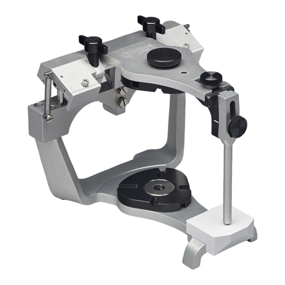
Page 9: The Denar Mark Ii Articulator (Semi-Adjustable)
II. THE DÉNAR ® MARK II ARTICULATOR In order to be proficient in the use of the To Open the Articulator articulator to diagnose condylar paths of Apply downward pressure to the top of movement and to fabricate occlusal the upper bow over the centric latch and... -
Page 10: Articulator Adjustments
To Lock in the Open Position rotating condyle which is simultaneous- ly rotating and moving outward during When the articulator is opened, the the mandibular side shift. upper bow can be moved downward orbiting path - the path of move- toward the lower bow so that the ment of the orbiting condyle. - Page 11 Protrusive Adjustments Progressive Side Shift Adjustment The inclination of the protrusive condy- The angle of inclination of the medial lar path can be adjusted by loosening fossa wall to the sagittal plane be the protrusive adjustment lockscrew. adjusted by loosening the progressive The protrusive condylar path inclination side shift adjustment lockscrew and scale is below the protrusive adjustment...
-
Page 12: Hand Grasps
(fig. 13). fig. 11 Rear Wall Inclination Rear The posterior fossa wall of the Mark II Wall Articulator is nonadjustable but is con- structed to average anatomic dimen- sions. It is inclined posteriorly 25... - Page 13 Underhand Pull Grasps To effect a left lateral mandibular move- ment the upper bow is moved to the right and pressure is applied with the left thumb to insure that the right orbit- ing condyle maintains contact with its superior and medial fossa walls and the left rotating condyle maintains contact with its superior and rear fossa walls (fig.
-
Page 14: Relating Condylar Movements To Occlusal Anatomy
III. RELATING CONDYLAR MOVEMENTS TO OCCLUSAL ANATOMY The Dénar ® Mark II Articulator is of the condyle and mandible move progres- Arcon construction; i.e., the condyles sively more to the right as the orbiting are attached to mandibular bow and the condyle advances. - Page 15 (fig. 25C). The Mark II Articu- fossa wall. lator cannot be adjusted to upward or downward movements of the rotating An increase of the immediate side shift condyle.
- Page 16 (ridge and groove direction). The Dénar ® Mark II Semi-adjustable Articulator has the rotating condylar path reset to the average anatomic inclination (out and backward 25 degrees). Figure 26A illustrates a frontal view of fig.
- Page 17 fig. 26 fig. 27 The closer the functioning tooth incline is Curve of Wilson. The more posteriorly we to the condylar path of movement the progress in the dental arches the more the tooth incline simulates that mandibular teeth take on a greater lingual condylar path of movement.The interrelat- inclination and the maxillary teeth take on ing tooth inclines on the orbiting side in...
- Page 18 fig. 28 To facilitate a clear understanding of the cusps. Three articulator controls estab- relation of the orbiting condylar path to lish the character of the orbiting path on the articulator __ the immediate side occlusal anatomy study fig. Illustrated are the cuspal inclines of the shift adjustment and the inclination of left bicuspids and molars which are the medial and superior fossa walls.
-
Page 19: The Immediate And Progressive Side Shift Adjustments (Bennett Shift)
SHIFT ADJUSTMENT (Bennett Shift) It should be noted that unlike most semi-adjustable articulators the Denar ® Mark II Semi-adjustable Articulator has the capability of more accurately simu- lating the mandibular side shift (Bennett Shift) by more accurately simulating the component condylar movements: the immediate side shift and the progressive shift. - Page 20 (Dénar ® Mark II) were adjusted so that the progressive side shift was pre-set to the average anatomic dimension of six degrees, one immediate side shift adjustment setting would intersect with all three condylar position checkbite records (A, B, and C) which remarkably...
-
Page 21: The Denar Mark Ii Facebow/Earbow (Model D31Ab)
1. Other reference material must be consulted for detailed instructions on how to precisely locate Procedures Manual __ Procedures for Occlusal ´ the terminal hinge axis position (i.e., the “Denar ® ´ Treatment” or the “Denar ®... - Page 22 fig. 33 fig. 34 Average measurement may be used to locate the posterior reference points whenever you do not vary the vertical dimension of the casts on the articula- tor, or, in other words, when the mandibular cast is to be transferred to the articulator by means of an interoc- clusal record taken at the correct verti- cal dimension and the vertical dimen-...
-
Page 23: Making The Facebow/Earbow Registration
Measure the distance between the ante- You will therefore notice that the hori- rior reference point and the inner can- zontal reference plane is identified on thus of the eye (fig. 36). Record this the face of the patient by two posterior measurement in the patient’s file for reference points in the area of the termi- future reference. - Page 24 fork in place (fig. 41). This can be done patient to maintain the bite fork in place most conveniently by having the patient with gentle biting pressure. bite on the index and middle fingers of the left hand. Alternatively position cot- Adjust the reference rod clamp so it is ton rolls on the occlusal surface of the parallel to the reference plane marked...
- Page 25 Clamp fig. 42 fig. 43 At this point you will be ready to attach dental structure to the posterior refer- the facebow side arms. Note that they ence points. The only thing remaining to are marked right and left and refer to the be done is to relate the maxillary dental patient’s right and left.
-
Page 26: Transferring The Facebow/Earbow To The Articulator
fig. 44 fig. 45 surfaces passes through the anterior Next secure a mounting plate to the reference point as well as the posterior upper bow of the articulator and a max- reference points (fig. 45). Then with your illary cast support to the lower bow (fig. left hand pull the locator to the side so 47). - Page 27 A. Facebow Transfer Attach the facebow (or earbow) assem- bly to the articulator by equally adjusting If the facebow/earbow is used as a face- both posterior reference slides so that bow (the posterior reference points are both scales give the same reading when oriented to the posterior reference the posterior reference pins are firmly points marked on the side of the...
- Page 28 seated in their respective condylar or earbow index holes. This can be done most conveniently by indexing both posterior reference pins in their respec- tive holes. Observe the setting to which the slides are adjusted. The sum of these settings divided by 2 is the setting to which the posterior reference slides are adjusted for proper transfer of the facebow to the articulator.
-
Page 29: Mounting The Casts In The Articulator
VI. MOUNTING THE CASTS IN THE ARTICULATOR The procedures for constructing casts stone to complete the mounting. The are not discussed in this manual. Once “two mix” procedure is recommend- you have obtained impressions of the ed to easily obtain a neat mounting. upper and lower arches for purposes of constructing the casts, you will in addi- Bring the upper bow down on top of the... -
Page 30: The Mandibular Cast
With the facebow application (not the mounting of the mandibular cast with earbow) it is usually easier to fill the the “one mix” or “two mix” procedure mounting plate with stone and stock a previously described. pile of mounting stone on the maxillary cast if the maxillary bow is removed and An alternate method of mounting the inverted on the working surface beside... - Page 31 fig. 58 fig. 59 support the mandibular cast, the fingers A recommended procedure is to initially are removed from the assembly. Sub- obtain three centric relation check-bite sequently the mounted mandibular cast records to verify the accuracy of the is removed and the mounting is com- centric relation mounting as detailed in pleted with the “two mix”...
-
Page 32: Setting The Articulator To Checkbite Records
(due to the fact that the patient’s orbiting paths of movement Mark II Articulator has the rotating from the two lateral checkbite records, condylar paths built to average anatom- and then diagnose and record the incli-... -
Page 33: Simulating The Protrusive Condylar Paths
articulator. A medialward adjust- ment of the right medial fossa wall (right immediate side shift adjust- ment of the articulator) allows for a mandibular side shift to the left. Repeat. It is important to note that the right immediate side shift adjustment refers to the articulator setting on the right side of the artic- ulator which allows for a mandibular... -
Page 34: Incisal Table Adjustments
VIII. INCISAL TABLE ADJUSTMENTS CUSTOM INCISAL TABLE adjustment at the foot of that incisal pin should be turned so that the rounded There are two different custom incisal end will more efficiently mold the acrylic. tables that fit Dénar ® Articulators. - Page 35 fig. 65 fig. 67 With the right index finger, push the foot tact the lingual surface of the upper of the incisal pin back until it just con- anterior teeth just lingual to their incisal tacts the inclined platform of the incisal edges.
- Page 36 fig. 69 fig. 71 Scale fig. 70 fig. 72 complement the anterior tooth relation- the table until it touches the foot of the ships in the following manner. Hold the incisal pin (fig. 72). Visually take a read- articulator in a right lateral mandibular ing on the front scale to note its angular position so that the right cuspids are in setting.
-
Page 37: Treatment Procedures
IX. TREATMENT PROCEDURES The rationale for utilizing the diagnostic condyle tracks a steeper protrusive and data obtained from protrusive and later- orbiting condylar path, the posterior al checkbite records is as follows. teeth will separate in both the protrusive excursion and in the lateral excursion on When the protrusive inclination of the the orbiting side. -
Page 38: Checkbite Procedure
APPENDIX A CHECKBITE PROCEDURE The mandibular cast is transferred to can be employed as circumstances dic- the articulator by: tate. 1. occluding it with the maxillary cast The following basic principles should 2. checkbite procedure always be employed in any checkbite 3. - Page 39 into anterior centric relation and gently guide the patient repeatingly in terminal hinge closure to lightly tap the soft wax to establish simultaneous contact of several mandibular teeth on the wax. The wax is removed from the mouth and chilled in tap water. The number of thicknesses of wax used should be the minimum number to effect posterior dis- clusion.
- Page 40 tent and not extended working time. It should have a flash set to a hard con- sistence that will fracture without warp- ing so the parts can be accurately reassembled if fractured. The material should be of a dead soft consistency when mixed but it must also have suffi- cient body to resist flow so that it will stay in place when positioned on the...
- Page 41 Once the set has the mounting for accuracy with the Denar ® Vericheck technique presented in Appendix B of this manual. The setting times of zinc oxide eugenol...
- Page 42 been timed the operator knows how long to pause after the media has been placed on the lower teeth before bring- ing the mandible to centric relation. It is desirable to bring the mandible to cen- tric relation just before the set occurs. For best results it is important that the operator and assistant work with consis- tent technique throughout this procedure.
- Page 43 retruded position and the orbiting number of additional strips of wax which condyle advanced approximately seven must be added to the lateral extremities millimeter. This can be done with the of the mandibular side of the wafer to “thumb on chin” method with the thumb establish even contact...
-
Page 44: Denar System Protocol For Dentist-Laboratory Relations
APPENDIX B DÉNAR SYSTEM PROTOCOL FOR DENTIST-LABORATORY RELATIONS The following protocol was developed arch casts in the position of maximum by a panel of experts in occlusal treat- intercuspation, the mounting procedure ment on the philosophy that a dentist could certainly be delegated to a dental seeking good laboratory support will auxiliary. - Page 45 are found to be satisfactory and occlusal discrepancies are identified in the mouth, the dentist is confident that the error was not introduced in the labo- ratory. He can then re-evaluate his pro- cedure to determine the source of error. In other words, if the restoration fits the mounted casts but not the mouth, the technician cannot be expected to par-...
- Page 46 Centric stops are on high spots or DISCUSSION low spots of cusps. Laboratory Fees and Instruments for 2. Tripod Contacts (. . .). Centric cusps Occlusal Treatment do not hit on their tips but are sup- The laboratory fee is for the time and ported by three or sometimes only skill which the technician employs in two centric contacts on the...
-
Page 47: Calibration Procedure
Field Inspection Gage to cal- handled carefully and not be allowed to ibrate the Dénar ® Mark II Semi- come to rest on a hard surface with a adjustable Articulator. It does not detail force which would cause a nick or the calibration procedure for the Dénar... - Page 48 When placing a gage component onto the bow of an articulator the index holes on the surface of the gage that faces the articulator bow should be carefully and visually located over their respective index pin on the bow of the articulator to prevent damage of the bearing surface of the gage.
- Page 49 fig. 88 the face of the maxillary bow, remem- bering to make sure that you rotate the scope in the same direction that you turn the lockscrew as you secure the scope to the face of the articulator. At this time the dial indicators will register “O”...
- Page 50 On the back of the stage is a calibration record as illustrated in figure 87. The two small circles on the lower portion of the record are the calibration records for the scope’s on the respective sides of the articulator. Each graduation off of the centric dot represents one thou- sandths of an inch (.001”).
- Page 51 This calibration system is used because RUN-OUT INSPECTION in manufacture, slight creepage of the PROCEDURE centric dot of the reticle can occur. This The articulator was aligned by means of calibration system allows for corrections the Field Inspection Gage with the pro- of this error and maximum accuracy.
- Page 52 fig. 93 fig. 94 Use of the inter-bow gage pin #2 requires a little care and skill. Therefore, after this adjustment is made be sure to check carefully to confirm that the inter-bow dimension of the gage pin was in fact transferred to the adjustable incisal pin.
-
Page 53: Occlusal Plane Analyzer
APPENDIX D OCCLUSAL PLANE ANALYZER The Broadrick Occlusal Plane Analyzer is used for analyzing the Curve of Spee The relatively small divergence between and developing an acceptable curve of arcs of 3 3/4”, 4”, and 5” radii over the occlusion, and is recommended for lab- functional occlusal surfaces on the oratory procedures employing the lower posterior teeth is shown in fig. - Page 54 (O.P.S.C.) will ultimately be located on some point on this arc. Select the posterior survey point (P.S.P.) at the disto-buccal cusp tip of the last lower molar (fig. 101). Should non molars exist, replace the upper cast and place soft modeling compound over the lower ridge and close the articulator until the incisal in contacts the incisal fig.
- Page 55 fig. 100 fig.101 or at the middle of the anterior margin of the hole on the lateral aspect of the condyle (fig. 102). Position the center point of the bow compass on the condylar posterior survey point (C.P.S.P.) and apply an arc with the graphite lead to intersect the arc formed from the A.S.P.
- Page 56 A plastic record card is now secured to the left side of the flag and marked “L.” Repeat the procedure commencing with figure 99 for the left survey. The scribing knife, as furnished, is for placement into the bow compass for scribing or cutting plaster, compound, or wax during the occlusal plane correc- tion.
-
Page 57: Selecting Instruments For Occlusal Treatment
Articulator and subsequently the the more pronounced condylar move- Dénar ® Mark II System and the Dénar ® ments of a given patient. These articula- Two Instrument System. tors were adjusted primarily to interoc- clusal records. - Page 58 are sufficient unprepared teeth to pro- nique, when indicated, can be used to vide positive stops and guidelines to produce excellent results. which to construct the restoration, the restoration can be constructed in har- To keep the discussion pertinent, it is mony with the existing occlusion and assumed that none of the patients in the the use of a pantograph is not neces-...
- Page 59 Mark II sequelae of bruxism (occlusal disease). System supplemented with the func- This patient first requires occlusal treat- tional generated path technique and/or ment and in addition, a three unit bridge.
-
Page 60: Accessories
APPENDIX F Dénar ® Semiadjustable Earbow/Facebow D31AB Bite Fork - Standard Articulator Dentulous Mark II Articulator Bite Fork - Edentulous (includes #300197 pin and D41AB platform) Anterior Reference Pointer Mark II-P2T2 Articulator (includes #110093 pin and D41 platform) Mark II-P2T3 Articulator... - Page 61 Maxillary Cast Support Remount Record Jig Mounting Plates Magnetic Mounting System Dawson Fossa-Guide Pin Pantograph Mounting Fixture...
-
Page 62: Care And Maintenance
APPENDIX G ARTICULATOR CARE AND MAINTENANCE ® Your Whip Mix Articulator is a precision WARRANTY instrument and requires care and main- Whip Mix Corporation warrants the tenance. Periodic cleaning and lubricat- articulator system to be free from ing as described below will assure pro- defects in material and/or workmanship longed life and dependable service from for a period of one year. - Page 68 ® Whip Mix Corporation - West 1730 East Prospect Rd., Suite 101 Fort Collins, CO 80525 Toll-Free: 1-800-201-7286 Fax: 1-970-472-1793 www.whipmix.com Denar ® and logo are registered trademarks of Whip Mix Corporation. ©2008 Whip Mix Corporation FN 80471-F AE R1008...
Need help?
Do you have a question about the Mark II and is the answer not in the manual?
Questions and answers