
Subscribe to Our Youtube Channel
Related Manuals for Byte Brothers TVR10/100/1000

Summary of Contents for Byte Brothers TVR10/100/1000
- Page 1 TVR10/100/1000 TRACE VERIFY REPAIR ● ● LAN TESTER ENDSPAN MIDSPAN Revision 4...
-
Page 2: Limited Warranty
PoE source. Damage may result. Made in the USA. Copyright 2011. TVR10/100/1000, TVR1000 , TVR and Test, Verify and Repair are trademarks of Byte Brothers, Inc. Model TVR10/100/1000 User's Guide Revision 4 Free DVD The TVR1000's big brother, the Real World Certifier, has a DVD de-... -
Page 3: Table Of Contents
Table of Contents Section I. Introduction ............The 10 Most Common Questions answered TVR10/100/1000 List of functions Section II. The Three phases of LAN installation ..... Section III. Faceplate description ........Section IV Learning the Main Unit's Faceplate ....10... -
Page 4: Section I. Introduction
Section I. Introduction. Negotiation makes networks work. Twisted pair cable is the standard for local area networks (LANs). Its popularity stems from its ease of use, cost, speed and maybe, most importantly, adaptability. A 10 Base-T device, installed years ago, communicates with a new gigabit switch (1000 Base-T) because the standard that defines Eth- ernet LANs requires negotiation to a common speed and duplex. - Page 5 LAN cabling questions answered... Is a hub/switch/PC connected to my cable? See example 4. Does my hub/switch/PC require 2 or 4 pair cable. See example 4. What pairs are terminated in my cable? See example 6. Where is my cable in the wiring closet? See example 5. What hub/switch port is my PC using? See example 5.
- Page 6 Multiple test sets in one tester: To accomplish its goals, the TVR1000 performs tests that, prior to the TVR1000, required 8 dif- ferent test sets. Plus, the multi-functionality is integrated to provide a combination of quick results that are not available in any other tester.
-
Page 7: Tvr10/100/1000 List Of Functions
TVR10/100/1000 ("TVR1000") List of Functions The TVR1000 performs the following functions: 10/100/1000 BASE-T LAN Tests: The TVR1000 plugs into active hubs, switches and PCs to verify 10, 100 and 1000 Base-T operation. Only the Main Unit is required for these tests. -
Page 8: Section Ii. The Three Phases Of Lan Installation
Section II. The Three Phases of LAN Installation For LAN installers and repair personnel. The TVR1000 is designed for both the LAN installer and the LAN repair person. The tests used during the three phases of LAN installation can just as well be used to repair LANs that are suffering operational problems. - Page 9 the Main Unit’s 10/100/1000 LAN Test jack (green bordered jack) directly into the device (use the supplied straight thru patch cable) and verify the equipment’s Device Type (i.e. is it a hub/switch or PC?); its maximum speed (10,100,1000 MB/s); duplex (full, half); and if PoE* is available for any devices that might require it.
-
Page 10: Section Iii. Faceplate Description
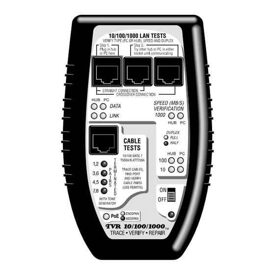
Section III. Faceplate Description. 10/100/1000 LAN TESTS The following tests utilize these 3 sockets. SPEED/DUPLEX LEDs... Shows 10,100 and/or 1000 MB/s. Color shows full or half duplex. Single port and inline mode. DATA/LINK LEDs...Verifies the device type (hub/switch or PC) and pres- ence of Data packets and/or Link pulses. -
Page 11: Main Unit
ENDSPAN MIDSPAN MAIN UNIT REMOTE PROBE... -
Page 12: Section Iv Learning The Main Unit's Faceplate
Section IV. Learning the Main Unit's Faceplate The TVR1000 Main Unit can be connected to a single port of any 10, 100 or 1000 Base-T device and it can be inserted inline between any two LAN devices without disrupting LAN communications. The Main Unit performs the bulk of the tests. - Page 13 communications, so the TVR1000 can be used to continuously monitor the link for data and link activity plus speed and duplex. Understanding the use of the 10/100/1000 LAN Test’s three RJ45 jacks. These jacks and associated LEDs are the heart of the Main Unit’s ability to save you time with your LAN tasks.
-
Page 14: Single Port Testing
Single Port testing Use the Green jack to verify the device type as a hub/switch or a PC; the presence of Data, Link pulses and PoE; and the speed and duplex capability of the device. First, turn ON the TVR1000. Then, plug the LAN device into the Green jack. -
Page 15: Inline Testing
Inline testing Use the three jacks to determine the negotiated speed and duplex between any two LAN devices. The multiple jacks pro- vide both a straight thru and a crossover connection (if required). The TVR1000 must be ON before plugging in devices. Using the two RJ45 straight thru patch cables provided with the TVR1000, plug two LAN devices into the leftmost jacks (making a straight thru connection between the two devices). - Page 16 testing) are the same for Inline testing. The speed/duplex indicated is the result of the two devices negotiating to a common speed and duplex. This is termed the "negotiated speed". Speed and Duplex are important considerations because two LAN devices will not to communicate unless they both are operating at the same speed and duplex.For more detailed information about Data and Link pulses see Appendix B.
- Page 17 Keeping in mind the above, the following applies: If the TVR1000 is connected to only one LAN device, it will ● display all of the device's speed and duplex capability. If the TVR1000 is placed inline between two LAN devices, it will ●...
- Page 18 CABLE TESTS Jack The Cable Test section of the Main Unit is an easy-to-use and very powerful part of the TVR1000. CAUTION: Do not plug the Cable Tests jack into PoE. Damage may result. Tone generator/Probe function: Places a tone (sequentially) on ●...
-
Page 19: Section V. Learning The Remote Probe's Faceplate
Section V. Learning the Remote Probe's Faceplate The TVR1000’s Remote Probe adds cable tracing and pairs testing capability to the TVR1000. It is used with the Main Unit’s Cable Tests jack. The Remote Probe traces cables and tests a cable's pair configuration by tracing signals placed on the cable by the Cable Tests jack (Main Unit). - Page 20 Main Unit’s Cable Test jack) and tracing it using The Remote Probe. The remote Probe will emit a tone when it is close to (or touching) the cable under test. Note: The tone generator places a tone on a pair of wires at a time (first 1,2 then 3,6 then 4,5 them 7,8).
- Page 21 same jack that transmits the tone) and displays the results of the decoding on the Remote Probe’s four LEDs. The LEDs meaning is defined by it labeling (“1,2”, “3,6”, etc); color (Off, Green or Red) and direction of scanning (top-to-bottom or bottom-to-top). Labeling: If the LED labeled “1,2”...
-
Page 22: Section Vi. Performing Lan Tests
Section VI. Performing LAN Tests What follows are a few examples of using the TVR1000 to perform typical network troubleshooting. With a little experience, you will be adding your own new tests. If you are new to LAN testing, please read the “Introduction”, “The Three Phases of LAN installation”, Appendix A, Appendix B and Appendix C of this manual. - Page 23 Plug into green jack PC or hub/switch ENDSPAN Straight thru patch cable MIDSPAN (included) SINGLE PORT METHOD PC or hub/switch Hub/Switch ENDSPAN MIDSPAN Main Unit's straight thru connectors are used in this example. "INLINE" METHOD...
- Page 24 Test example #1. Using a Single Port test to determine a PC or Hub/Switch's capabilities. Tests if a LAN port is ON and capable of transmitting; verifies its Device Type (hub/switch or PC); displays its Speed and Duplex (a 10,100,1000 device lights all 3 speed LEDs);...
- Page 25 Step 4: SPEED/DUPLEX TEST: The data rate(s) of 10,100 and 1000 MB/s are displayed on the Main Unit’s “SPEED VERIFICA- TION” LEDs. The color of the LEDs define the duplex (Full or Half). If you are testing a device that is capable of multiple speeds and duplexes, all appropriate LEDs will light.
- Page 26 If the data rate is less than you expect (e.g. a 100 MB/s communi- cating at 10 MB/s), look for one of these problems: The LAN device is a 10 Base-T port only. ● There is a “Cable Fault.” A cable fault is when a wiring pair is ●...
- Page 27 allow a minimum of 3 seconds between connections (this is the time it takes the TVR1000 to make a reading). Step 3. Get them communicating: Study the “DATA” and"LINK" LEDs. If communicating, a LED will be ON in both columns (“HUB” and “PC”).
- Page 28 the negotiated speed/duplex of the two devices is slower than the speed/duplex of each individual device (you determine the speed and duplex of the individual devices by plugging them separately into the Green jack as shown in the Single Port test of Example#1). As an example, if one of the devices is 1000 MB/s, full duplex and the negotiated speed between the two devices is 100 MB/s, half duplex, you know that something is pulling the 1000 Base-T device...
- Page 29 If only one column of LEDs comes on in either jack configuration you are not communicating. If this is the case, unplug both devices from the TVR1000 and then test the devices individually using the Green jack. The device that does not show any activity on the LEDs is causing the problem.
-
Page 30: 10/100/1000 Lan Tests Section
Test example #3. Testing a 100 MB/s switch port for an un- known problem at far end of the cable (not at the switch port). This test uses the 10/100/1000 LAN TESTS section of the Main Unit to test the speed and wiring of the connection. Step 1: Turn ON tester. -
Page 31: Cable Tests Section
between) and test. You should see activity (a Data/Link LED) and a Speed/Duplex LED. If you don't, the LAN device is faulty. If you do, the cable is faulty. Test example #4. TEST for Hub/Switch or PC at the far end of a cable using the TVR1000’s Cable Test Jack (continuity test). - Page 32 senses if the far device is connected to the cable by searching for continuity through the device. It does not matter if the far device is powered-up or not. Step 1: Turn tester ON and connect the jack that connects to the hub/switch or PC to the TVR1000’s Cable Tests jack as shown.
-
Page 33: Test Example #6. Testing A Cable's Pair Configuration
“7,8’). Listening to the missing gaps in the tone signal can some- times be helpful in understanding a problem. Maximum sensitivity occurs when the Remote Probe’s tip is held parallel to the conductors carrying the tone. It is normal for the volume to change along a cable's path (volume can change as the cable length changes;... - Page 34 (see Appendix A). See note below for required pairs. INVERTED PAIRS: If any of the pairs are present but have incorrect polarity (i.e. the “1,2” pair is really “2,1”) the pair’s LED will light red. Inverted pairs can slow down or stop a link. PAIR NOT PRESENT: The LEDs will not light, if the pair does not exist or if the pair is shorted across itself.
-
Page 35: Appendix A. Wiring Primer
Appendix A. Wiring Primer. Twisted Pair Cable: Base-T LANs are based on a star topology (every PC on the network is linked to a central location). The central location is termed a hub or switch. The cabling is always twisted pair wire terminated with 8 position modular connectors (RJ45). - Page 36 Summary Twisted Pair (TP) Wire Connection Chart Twisted Pair cables connecting: PC to Hub/Switch Straight thru PC to PC Crossover Hub/Sw to Hub/Switch Crossover Note: Because the Base-T standard has a mix of crossover and straight thru cables, many opportunities arise for the pairs to get “flipped.”...
- Page 37 AT&T 258A (EIA/TIA 568B) STRAIGHT THRU PIN # PIN # WIRE COLOR 1 Orange/White 2 Orange 3 Green/White 6 Green 4 Blue 5 Blue/White 7 Brown/White 8 Brown Colors: First color is the base color of the cable. The second color is the stripe on the cable.
- Page 38 AT&T 258A (EIA/TIA 568B) Signal Definition in Diagram Form PIN # POLARITY FUNCTION Pair 2 (+) Transmit Data (-) Receive Data Pair 3 (+) Transmit Data (-) Receive Data Pair 1 (-) Receive Data (+) Transmit Data Pair 4 (+) Transmit Data (-) Receive Data Mixing Telephones and Data: Some installations mix Base-T networks on the same wires that are used in a telephone system.
- Page 39 Twisted Pair Cables TP cable is used for Base-T applications be- cause of its excellent noise cancelling capabilities. Two pairs of twisted pair wire are the minimum required for each computer that hooks to the hub or switch : One pair of TP wire to transmit data to the hub. ●...
- Page 40 RJ45 Connectors (sockets and plugs): The Base-T Standard uses RJ45 sockets and plugs. The RJ45 socket has 8 pins. The pins are numbered 1 to 8. Looking at the socket with insertion key facing down, pin number 1 is to the left. There are two types of RJ45 plugs: One specifically for CAT6 (has offset contacts) and another for CAT5E and below.
-
Page 41: Appendix B. 10, 100 And 1000 Base-T Basics
Appendix B. 10, 100 and 1000 Base-T Basics Base-T LANs connect LAN devices (PCs, hubs and switches) to other LAN devices using twisted pair cable. The speed and duplex of the individual devices (and the proper cable) determine the per- formance of the LAN. - Page 42 "Hub", "Switch" and "PC" defined: A “PC” is a device that transmits on a pair of wires that use pins 1 and 2 (“1,2”). A “hub” and "switch" are devices that transmit on pins 3 and 6 (“3,6”). When the TVR1000 senses a link pulse or data packet, it lights the Data and Link LEDs on the faceplate to indicate its source (hub or PC) based on the above standard.
- Page 43 some devices are programmable, allowing you to "force" their speed and duplex. "Forced" devices, likewise, may not send link pulses. Because the TVR1000 uses link pulses to determine the speed and duplex, if there is no link pulse, no speed LEDs will light. This does not mean that the devices cannot communicate.
- Page 44 (is it Cat 5E? is it Cat 6?) and printing test results, take a look at the Byte Brothers Real World Certifier at www. bytebrothers.com. It has all of the features of the TVR1000 plus ad-...
-
Page 45: Appendix C. Ways To Minimize Lan Problems
Appendix C. Ways to minimize LAN problems. Use Category 5E cable (rated at 1000 MB/s). ● Connect all four pairs when installing cables. ● Use straight thru connections for installed cables. ● Install all cables using standardized color code. ● Use color coded patch cables with all four pairs wired. -
Page 46: Appendix D. Self-Test And Battery Replacement
Appendix D. Self test and battery replacement Testing the Main Unit: The “10/100/1000 LAN Test” section of the Main Unit is equipped with a self-test feature that is automati- cally activated when the unit is powered ON. Self-test progress is indicated by a series of sequentially flashing LEDs. - Page 48 © 2011 Byte Brothers, Inc. www.bytebrothers.com Network Test and Certification Network Test and Certification 7003 132nd Place SE, Newcastle, WA 98059 USA +1.425.917.8380 FAX +1.425.917.8379 cs@bytebrothers.com ● ●...
Need help?
Do you have a question about the TVR10/100/1000 and is the answer not in the manual?
Questions and answers