Table of Contents
Advertisement
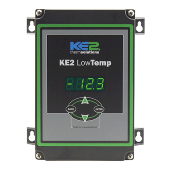
KE2 Low Temp+Defrost
Quick Start Guide
This reference should remain on site with the installed KE2 Low Temp + Defrost controller.
A
D
E
F
H
Parts List
The following parts are included in the KE2 Low Temp
controller kits:
Kit # 20903 with 120/208-240 VAC controller
A
(1) KE2 Low Temp controller
B
(1) high voltage safety shield
C
(2) temperature sensors
D
(6) 90° spade connectors
E
(2) straight spade connectors
F
(5) self-tapping screws
G
(1) 1/2" plastic knockout plug
H
(1) air sensor mount
I
(3) coarse thread screws
J
(1) controller programming sticker
(1) Warranty card
(not shown)
Accessories to Aid in Installation
The following parts are available separately:
(1) Wire Harness - 10' pn 20736, 25' pn 20670 or 40' pn 20737
(1) KE2 Terminal Board* pn 20996
Further information is found in KE2 Therm Condensed Catalog 411.
* When used with the KE2 Low Temp controller, the fuses must be sized to match the
application (i.e. Replace existing fuses with 30 Amp Time Delay fuses for fans and
compressor)
© Copyright 2017 KE2 Therm Solutions, Inc., Washington, Missouri 63090
(pn 20903)
B
J
I
G
Supplies List
The KE2 Low Temp is supplied with all of the accessories required for
the controller to work, however, standard truck stock items will also
be required to install the controller. To simplify the installation, a list
of items has been provided.
Unique Features:
Service Call Saver - Post Defrost Indicator
To eliminate unnecessary service calls, the KE2 Low Temp alerts the user
when it is coming out of a defrost cycle using the onboard display. The
display alternates between dEF and the actual temperature measured
by the air sensor. This continues until the temperature reaches setpoint,
or for the amount of time set by dFt (Defrost Time) whichever is shorter.
The KE2 Low Temp includes RS-485 Modbus communications, and can
now be accessed remotely using the KE2 Local Area Dashboard and
Alarms (KE2 LDA). See page 14 for additional details.
Additional Inputs -
Visit our YouTube channel for
videos related to the KE2 Low
Temp + Defrost.
C
Video 042 Wiring the KE2 Low Temp
Video 043 Configure the KE2 Low
Video 068 How to Determine Proper
Video 069 How to Properly Install a
Conduit to go between the controller and the evaporator
(2) Conduit connectors (straight or elbow as required)
(8) High voltage wires matched to the load of the heaters,
fans, liquid line solenoid, and the controller.
(8) Spade Connectors matched to the gauge of high voltage
wires
Wire labeling (numbers, colors, etc.)
Wire ties
18 gauge twisted shielded pair (if extending sensor wires)
and suitable for RS485 communication
Foam insulation if running wires outside the space.
Silicone (for sealing any box penetrations)
e.g. Door switch and additional sensors
Q.3.29 (Q.1.29)
May 2017
or KE2 Adaptive Control
for a Door Switch
Temp or KE2 Adaptive
Control for a Door Switch
Coil Sensor Location
Coil Sensor
youtube.com/ke2therm
Advertisement
Table of Contents

Summary of Contents for KE2 Therm Solutions KE2 Low Temp Plus Defrost
- Page 1 KE2 Local Area Dashboard and compressor) Alarms (KE2 LDA). See page 14 for additional details. Additional Inputs - e.g. Door switch and additional sensors © Copyright 2017 KE2 Therm Solutions, Inc., Washington, Missouri 63090...
- Page 2 (calculated from Suct. Pressure) Saturation Temp °F TEV or EEV (from receiver pressure) Superheat ° Hot Vapor Liquid Temp at Valve °F Condenser Subcooling ° Discharge Pressure Warm Liquid Compressor Warm Air AMPS © Copyright 2017 KE2 Therm Solutions, Inc., Washington, Missouri 63090...
- Page 3 Item G from Parts List on page 1 housing to access the coil. Installer must puncture plug to insert sen- sor wire. Make note of the location you have determined for placement of the coil sensor. © Copyright 2017 KE2 Therm Solutions, Inc., Washington, Missouri 63090...
- Page 4 Note: KE2 Therm offers pre-made wiring harnesses to simplify installation. Each harness contains the proper color coded and sized wires, with flag terminals already installed. Refer to the ac- cessories listed on page 1. © Copyright 2017 KE2 Therm Solutions, Inc., Washington, Missouri 63090...
- Page 5 Crimp on female spade connectors (Item E from list on page 1) Plug into the board as indicated in Wiring Schematic. Note: All terminals should be crimped to withstand 30lb pull test. © Copyright 2017 KE2 Therm Solutions, Inc., Washington, Missouri 63090...
- Page 6 Locate 2 90° female spade connectors in the accessories kit. Crimp on the female spade connectors. Plug the connectors to the COM and NO positions of the Fan Relay. Confirm combined fan motor load is not over 30 FLA. © Copyright 2017 KE2 Therm Solutions, Inc., Washington, Missouri 63090...
- Page 7 Verify power is no longer present using a multimeter. Evaporator wiring Now that the conduit is prepared, it can be connected to the evaporator. Locate the proper sized knockout and carefully remove knockout. Connect conduit to the evaporator © Copyright 2017 KE2 Therm Solutions, Inc., Washington, Missouri 63090...
- Page 8 See Figure 2 be- low, and step by step instructions 14 - 19 on the following pages. Figure 2 - Wiring Schematic - Using KE2 Terminal Board © Copyright 2017 KE2 Therm Solutions, Inc., Washington, Missouri 63090...
- Page 9 Fan Relay to one set of the fan leads. This wire will be connected to the NO of the fan relay on the controller. Connect L2/Neutral to remaining fan leads. © Copyright 2017 KE2 Therm Solutions, Inc., Washington, Missouri 63090...
- Page 10 Attach the yellow wire with black stripe connects to the NO terminal on the L.L. Solenoid/Compressor re- lay to a solenoid lead Connect L2/Neutral to the remain- ing L.L. Solenoid/Compressor lead. © Copyright 2017 KE2 Therm Solutions, Inc., Washington, Missouri 63090...
- Page 11 Do not allow the metal portion of the air sensor to touch any- thing other than air. It should not touch the bracket, nylon cable tie, or any other solid surface. © Copyright 2017 KE2 Therm Solutions, Inc., Washington, Missouri 63090...
- Page 12 High voltage is defined by Underwriter’s Laboratories as above 30V. If crossing a high voltage line is necessary, the sensor wiring should be run at right angles to prevent noise. © Copyright 2017 KE2 Therm Solutions, Inc., Washington, Missouri 63090...
- Page 13 The KE2 Low Temp includes RS-485 Modbus communications, and can now be accessed remotely using the KE2 Local Area Dashboard and Alarms (KE2 LDA). See page 14 for further details. © Copyright 2017 KE2 Therm Solutions, Inc., Washington, Missouri 63090...
- Page 14 KE2 LDA to KE2 Smart Access Video 061 What information is on the KE2 LDA’s Dashboard and Manage- ment Console Video 062 Communication Made Easy with KE2 Smart Access youtube.com/ke2therm © Copyright 2017 KE2 Therm Solutions, Inc., Washington, Missouri 63090...
- Page 15 2nd Auxiliary input (AU2) is used trdF or dtsP indF or dFLo or drnt dFin or Fndf t2nd or dOOr or SYOF or dtSP COiL or drnt SySt FdSP CPrl Fndt dFrl FndF Fnrl ALSt © Copyright 2017 KE2 Therm Solutions, Inc., Washington, Missouri 63090...
- Page 16 To move between the setpoint displayed and its associated value, re- quires a momentary press of the Enter button. To return to the value press the BACK button. Changing Setpoints © Copyright 2017 KE2 Therm Solutions, Inc., Washington, Missouri 63090...
- Page 17 Fan State During Defrost OFF if Elec; On if Air On FndF High Alarm Offset 0° 10° 50° Low Alarm Offset 0° 4° 10° Temp Alarm Delay 1 min 90 min 180 min © Copyright 2017 KE2 Therm Solutions, Inc., Washington, Missouri 63090...
- Page 18 Alarm state - noAL (no alarm), AtSA (air sensor), CLSA (coil sensor), AU1A (aux input 1 alarm), AU2A (aux input 2 alarm), HtA ALSt ALSt (high temp alarm), LtA (low temp alarm), dOOr (door open), PF (power failure) © Copyright 2017 KE2 Therm Solutions, Inc., Washington, Missouri 63090...
- Page 19 Amount of time in drain mode Defrost Term Temperature dtSP dtSP Setpoint Coil temperature reaches defrost term temperature setpoint to terminate defrost Setpoint dtyP dtyP Type of Defrost Setpoint Air or Electric © Copyright 2017 KE2 Therm Solutions, Inc., Washington, Missouri 63090...
- Page 20 Alternate room temperature setpoint Temp units Setpoint Fahrenheit (FAH) or Celsius (CEL) © Copyright 2017 KE2 Therm Solutions, Inc., Washington, Missouri 63090 KE2 Therm Solutions Q.3.29 May 2017 supersedes Q.1.29 November 2014 and all prior publications. 12 Chamber Drive . Washington, MO 63090...