Table of Contents
Advertisement
Advertisement
Table of Contents

Summary of Contents for e-motion nGauge
- Page 1 Instruction Manual v1.14...
-
Page 2: Table Of Contents
5.1 Installing Files From SD Card ......................13 5.2 Installing Files From PC or MAC ..................... 13 5.3 Adjusting Standard/Metric Units ....................14 5.4 Display Brightness .......................... 14 5.5 Default Power-up Screen ....................... 14 nGauge Instruction Manual v1.14 | © 2017 E-Motion Products, LLC... - Page 3 6.1 Connections and Wiring ......................... 16 6.2 Analog Input Driver Setup ......................16 7 Updating nGauge ........................ 18 Appendices ..........................19 Appendix A: Accessory Cable Pin Out ....................19 Limited Warranty ........................21 nGauge Instruction Manual v1.14 | © 2017 E-Motion Products, LLC...
-
Page 4: List Of Revisions
2016-04-14 Corrected company name 1.12 2016-05-12 5.4, 5.6, 5.7 Added Sleep/Wake, and Reset Settings sections 1.13 2016-07-28 5.4, 3.4, 3.5 Added Round Gauge specifics 1.14 2017-09-27 Added Touch Calibration section nGauge Instruction Manual v1.14 | © 2017 E-Motion Products, LLC... -
Page 5: Important Notes
Code Section 26708(a)). E-Motion does not take any responsibility for any fines, penalties, or damages that may be incurred as a result of disregarding the laws and statutes of the jurisdictions in which a nGauge is operated. Similar laws may apply within your province or state. Please verify your provincial or state laws prior to installation. -
Page 6: Pre-Installation Notice
Any damage caused by improper cable routing is not covered under the nGauge limited warranty. 1.2 ATTACHING WINDSHIELD MOUNT Mount the nGauge on the windshield in a spot that does not obstruct the view of the road or in any way that interferes with the safe operation of the vehicle. -
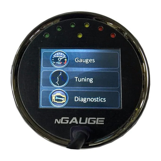
Page 7: Basic Operation
The home screen contains Gauges, Tuning and Diagnostics tabs. 2.2 NEW VEHICLE SETUP/FIND SIGNALS The nGauge has been designed to be used on most 1996 and newer OBD II vehicles. Vehicles to which the nGauge is connected, will typically offer a different set of parameters or signals available. -
Page 8: Gauge Setup & Navigation
3 GAUGE SETUP & NAVIGATION The nGauge offers the ability to monitor vehicle sensors for real time display and data logging. Data sample rates will vary by vehicle. This rate is a fixed amount and the total of active signals being monitored and logged will share this sample rate. -
Page 9: Set Minimum/Maximum/Scaling (Round Gauges Only)
Minimum refers to the preferred low end value of the gauge, and the Maximum refers to the preferred high end value of the gauge. The algorithm in the nGauge rounds user-entered values if necessary. The figure in this section shows the Round Gauge display and how the Min/Max, Scaling, and Low/High Warnings are implemented. -
Page 10: Data Logger
3.6 DATA LOGGER The nGauge will monitor and log all signals shown on the active gauge screen. It is also possible to monitor signals not shown on the active gauge screen. This allows the user to view only the most valuable data, while still being able to review all the vehicle data in the log file. -
Page 11: Using Zeitronix Products
3.7 USING ZEITRONIX PRODUCTS If you are going to use a Zeitronix wideband, the nGauge comes with a Zeitronix driver that uses the serial port to connect digitally to the Zt-2 controller. This is the preferred way to connect the Zt-2 wideband as compared to connecting the wideband voltage to the nGauge Analog Input. -
Page 12: Data Logging In Gauges
Tap [End Log] when finished logging session. The data is now saved to the memory card. Each time a data logging session is started and ended, nGauge saves one file to the SD memory card in a directory called “logs.” Each saved file has a log prefix. -
Page 13: Diagnostic Code Reader
Note: Clearing codes does not solve any underlying vehicle issues. Tap [Yes] to clear the code(s) and turn the check engine light off. Tap [No] to leave the code(s) set and leave the check engine light on. nGauge Instruction Manual v1.14 | © 2017 E-Motion Products, LLC... -
Page 14: Customizing Your Ngauge
PC will “ding” once PC recognizes device Open window with computer drives i.e. C:, D:, etc. Identify the letter for nGauge. Drag and drop the file onto the correct drive associated with the nGauge Copy and Paste can also be used Allow the file to transfer After the file has transferred, use the PC’s function to “Safe Eject”... -
Page 15: Adjusting Standard/Metric Units
Select the desired brightness level. 5.5 DEFAULT POWER-UP SCREEN nGauge allows you to easily change which screen appears on initial power-up of the nGauge. This can help make it faster and easier to navigate through the nGauge to find the functions you use most. -
Page 16: Reset Settings
Navigate to [Diagnostics], [Settings], [Calibrate Touch] At the main menu (showing Gauges, Tuning, Diagnostics), tap and hold for 5 seconds If touch accuracy issues are still present after recalibrating, or if the nGauge is unable to perform all these actions, please contact support. -
Page 17: Ngauge Analog Inputs
2 terminal resistive temperature sensors are usually non-linear. 6.1 CONNECTIONS AND WIRING Connect the analog input signal you wish to measure to either Analog In 1 or Analog In 2 on the nGauge. See Appendix A: Accessory Cable Pin Out for the I/O cable wiring table. - Page 18 User Decimals: How many decimals to display. Leaving this blank or entering 0 will display 1.256 as 1. Entering 1 will display 1.256 as 1.3. Entering 2 will display 1.256 at 1.26. nGauge Instruction Manual v1.14 | © 2017 E-Motion Products, LLC...
-
Page 19: Updating Ngauge
Via USB to nGauge connection: Connect nGague to PC via USB cable. Go to "Settings > USB SD" in your nGauge menus. nGauge should then be recognized as a drive by your PC. iii. Place the downloaded firmware file on the root of your SD Card. Do not rename the file. -
Page 20: Appendices
APPENDICES APPENDIX A: ACCESSORY CABLE PIN OUT For nGauge serial numbers below 20,000: nGauge Instruction Manual v1.14 | © 2017 E-Motion Products, LLC... - Page 21 For nGauge serial number 20,000 and up: nGauge Instruction Manual v1.14 | © 2017 E-Motion Products, LLC...
-
Page 22: Limited Warranty
LIMITED WARRANTY E-Motion LLC guarantees that every nGauge is free from physical defects in material and workmanship under normal use for one year from the date of purchase. If the product proves defective during this warranty period, contact your nGauge distributor in order to obtain a Return Authorization number and form.
Need help?
Do you have a question about the nGauge and is the answer not in the manual?
Questions and answers