
Related Manuals for ISA CBA2000


Summary of Contents for ISA CBA2000
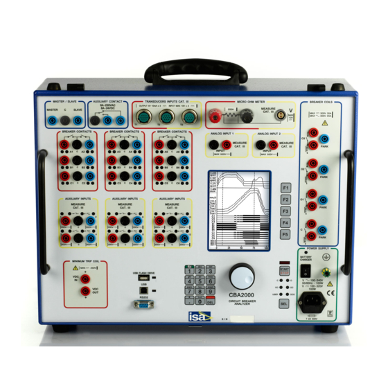
- Page 1 DATE: 19/03/2015 DOC.SIE10169 REV.13 CIRCUIT BREAKER ANALYZER AND MICROOHMMETER MOD. CBA2000 PowerMeterStore 1.877.766.5412 www. Shop for Power Metering products online at:...
-
Page 2: Table Of Contents
Doc. SIE10169 Rev. 13 Page 3 of 32 APPLICABLE STANDARDS ............................4 1 INTRODUCTION ............................... 5 2 CHARACTERISTICS ..............................8 2.1 C ............................8 OIL DRIVING CIRCUITS 2.2 M ............................. 8 AIN CONTACT INPUTS 2.3 A ..........................8 UXILIARY INPUTS AND OUTPUTS 2.4 I ................................ -
Page 3: Applicable Standards
Doc. SIE10169 Rev. 13 Page 4 of 32 APPLICABLE STANDARDS The test set conforms to the EEC directives regarding Electromagnetic Compatibility and Low Voltage instruments. A) Electromagnetic Compatibility: Directive no. 2004/108/EC. Applicable Standard : EN61326-1 + A1 + A2. EMISSION - EN 61000-3-2 + A2: Harmonic content of power supply. -
Page 4: Introduction
Page 5 of 32 INTRODUCTION The circuit breaker analyzer and microOhmmeter model CBA2000 is a two-in-one test set. When used as a circuit breaker analyzer, it allows the off-line testing of the characteristics of all modern MV and HV circuit breakers. The test set measures CB operation times as they are defined in the IEC standard 62271-100;... - Page 5 All circuits have been designed to ensure safe operation in the noisy environment of HV and MV substations. The instrument is housed in a transportable aluminium box, that is provided with removable cover and handles for ease of transportation. The following table lists he key new features of CBA2000 with respect to CBA1000. PERFORMANCE CBA2000 CBA1000 COIL DRIVING 2;...
- Page 6 Doc. SIE10169 Rev. 13 Page 7 of 32 NOTE: WINDOWS is a trademark of MICROSOFT inc. PowerMeterStore 1.877.766.5412 www. Shop for Power Metering products online at:...
-
Page 7: Characteristics
Doc. SIE10169 Rev. 13 Page 8 of 32 CHARACTERISTICS 2.1 C OIL DRIVING CIRCUITS . Number of circuits: two; optionally four. . Type of driver: electronic; it ensures superior timing control. . Driver characteristic: 300 V DC max; 30 A DC max; 300 V AC max; 20 A AC max. . -
Page 8: Inputs Timing
Doc. SIE10169 Rev. 13 Page 9 of 32 2.4 I NPUTS TIMING . Sample rate: from 20 kHz maximum, for recording up to 1s to 20 Hz, for recording up to 1s 1000 s. See the table below for more details. . -
Page 9: Digital Transducers
. External trigger. The test set features a Trigger Out output and a Trigger In input, that allow synchronizing up to 4 CBA2000’s. In this mode, one CBA2000 acts as the Master unit; its Trigger Out output will be connected to all other units, selected as Slave. As the Master starts the test, all other Slave units will measure the timing on Main, auxiliary and analog inputs. -
Page 10: Static Resistance Measurement (Optional)
2.8 S (OPTIONAL) TATIC RESISTANCE MEASUREMENT This measurement is performed connecting CBA2000 to the test sample and measuring its resistance. Test samples can be: joints, main contacts and so on. Main contacts resistance is measured in the closed position. . Test current, resistance measuring range, resolution and accuracy: see the table. -
Page 11: Dynamic Resistance Measurement (Optional)
With this measurement it is possible to record the main contact resistance during the CB close. The CB is open prior to test start: CBA2000 issues the Close command; as the contact closes, the test current passes through the contact, and CBA1000 measures the contact resistance variations during the close movement. -
Page 12: Pc Software
. Enhanced measurement features for movement – speed – acceleration control. The software will be upgraded for free until a new version is released. Upgrading is simple: just connect to the ISA WEB site, and download the latest version. This applies also to the test set resident program. -
Page 13: Other Characteristics
Doc. SIE10169 Rev. 13 Page 14 of 32 2.14 O THER CHARACTERISTICS . Mains supply: .. From 85 to 265 V AC; 50-60 Hz, .. From 100 to 350 V DC. . Maximum supply current: 1.5 A @ 85 V AC; power consumption 85 VA. . -
Page 14: Options
The option is made of an additional printed circuit board that fits into the mother board. Even if it is possible to upgrade CBA2000, it is advisable to request the option at order. 3.3 A DDITIONAL MAIN AND AUXILIARY INPUTS This option adds to the test set two main contact sensing circuits each phase and four auxiliary digital event inputs . -
Page 15: Basic Connection Cables Set ; Option Pii15169
1. Three cables with silicone isolator for the connection to the main contacts, each of three conductors. Cable length: 16 m; cross section 1 sq. mm. Terminated on the CBA2000 side with safety banana sockets, with colors: black, red, blue, and on the CB side with three clamps, with the same colors. - Page 16 Cable length: 10 m; cross section 0,5 sq. mm. Terminated with the suitable connector on the CBA2000 side, and with two clamps on the CB side. 5. One set of crocodiles, 16 in all, with different colors, for the connection to auxiliary contacts and for the 500 V measurement inputs connection.
- Page 17 12. Three 10-way cables for the connection to digital transducers. Length 1 m; terminated with a 10-way connector on the CBA2000 side, and with seven banana sockets on the other side.
-
Page 18: Long Connection Cables ; Code Pii81169
If the micro-ohm meter option is included, the following connection cables are provided: .. Two high current cables, made of one conductor. Cable length: 10 m; cross section 25 sq. mm. Terminated with a suitable terminator on the CBA2000 side, and with an high current clamp on the CB side. -
Page 19: Transit Case
Cable length: 10 m; cross section 1 sq. mm; terminated with safety banana sockets, with colors: black, red, blue. 3.10 T RANSIT CASE The transit case allows delivering CBA2000 with no concern about shocks up to a fall of 1 m. Protection degree: IP 65. PowerMeterStore 1.877.766.5412 www. -
Page 20: Soft Protection Bag
Besides, if the Circuit Breakers has a graphite nozzle, CBA2000 displays the timing at which the graphite is engaged, and when the main contact is reached, thus allowing to check the deterioration of the graphite. - Page 21 - Each head has one 8 m long cable, terminated with a multi-pole connector, for the connection between the remote head and the BSG Main unit. . No 1 BSG Main unit connected to the CBA2000 breaker analyzer. . No 1 Cables kit made of: - N.
- Page 22 Page 23 of 32 . Maximum test duration (each test): 1 s. . Graphite nozzle test selection in the CBA2000 menu. In this instance, the contact with the graphite is displayed as an intermediate thickness line. The relevant timings are reported.
-
Page 23: Position Transducers
Doc. SIE10169 Rev. 13 Page 24 of 32 3.13 P OSITION TRANSDUCERS 3.13.1 Analog transducers We have a set of analog transducers, linear and rotating. Linear transducers have different strokes, and also different IP protections: low for the TLH series, high for the LWG series. A mounting kit is also available. -
Page 24: Digital Transducers
Doc. SIE10169 Rev. 13 Page 25 of 32 3.13.2 Digital transducers The digital transducer option has the following characteristics. . Transducer name: HENGSTLER RS0-550-170; . Transducer type: RS422 interface; 5000 impulses per turn; . Connection: the transducer is connected to the test set via a shielded cable, 10 m long, terminated with a connector. -
Page 25: Ac Current Clamp , Code Pii88169
. Mounting: via an M12 plug, 10.5 mm long; . Connection to CBA2000: via a 10 m long cable, provided, terminated with the four-poles female connector on the transducer side, and with the 10 poles male connector on the CBA side;... - Page 26 Doc. SIE10169 Rev. 13 Page 27 of 32 . Once connected, CBA2000 provides the power supply, and the transducer is ready for the measurement. PowerMeterStore 1.877.766.5412 www. Shop for Power Metering products online at:...
-
Page 27: Protections
Doc. SIE10169 Rev. 13 Page 28 of 32 PROTECTIONS - Fuse on the mains supply. - At power-on, a diagnostic sequence controls the microprocessors. If something is wrong, the operator is alerted by a message. - The test is started pressing the START pushbutton, and then also pushing the multifunction knob. - During the test, the circuits driving the coils give alarm messages in case of: selected current range exceeded (short circuit included);... -
Page 28: Appendix A: Menu Selections
Doc. SIE10169 Rev. 13 Page 29 of 32 APPENDIX A: MENU SELECTIONS LEVEL 1 LEVEL 2 LEVEL 3 LEVEL 4 1 TRIGGER OPTIONS 1 Coil current % of range (1 to 99) 2 Coil command 3 Coil command reset 4 Analog input 1 Threshold, positive or negative 2 input range... - Page 29 Doc. SIE10169 Rev. 13 Page 30 of 32 LEVEL 1 LEVEL 2 LEVEL 3 LEVEL 4 4 BREAKER AND 1 Breaker contacts AUXILIARY CHANNEL A1+B1+C1; SETTINGS 2 Pre-insertion Enable/disable resistor test 3 Auxiliary inputs Enable/disable; Label; Dry/wet 4 Auxiliary inputs Enable/disable;...
- Page 30 Doc. SIE10169 Rev. 13 Page 31 of 32 LEVEL 1 LEVEL 2 LEVEL 3 LEVEL 4 From closed to open At open position At closed position At CB opening A point set-up B point set-up 4 Pressure Input: 5 V, 500 V transducer 1 U.M.
- Page 31 Doc. SIE10169 Rev. 13 Page 32 of 32 LEVEL 1 LEVEL 2 LEVEL 3 LEVEL 4 8 PREFERENCES 1 Date and time 2 Display 1 Contrast 2 Backlight duration 3 Time measurement ms; 60 Hz cycles; 50 Hz cycles 4 Debounce 5 Buzzer Yes - No 6 Print diagrams...
Need help?
Do you have a question about the CBA2000 and is the answer not in the manual?
Questions and answers