Table of Contents
Advertisement
Mi-TIC User Manual
www.argusdirect.com
Whilst Avon Protection has taken care to ensure the accuracy of the information contained herein it accepts no responsibility for the consequences of any
use thereof and also reserves the right to change the specification of goods without notice. Avon Protection accepts no liability beyond the set out in its
standard conditions of sale in respect of infringement of third party patents arising from the use of tubes or other devices in accordance with information
contained herein.
Avon Protection, Hampton Park West, Semington Road, Melksham, Wiltshire, SN12 6NB Telephone: +44 (0)1225 896705
Contact argus by e-mail: argus@avon-protection.com or visit
www.argusdirect.com
© Avon Protection
GR 13313
DAS775571AA Version 9, December 2015
CR121804
Advertisement
Table of Contents

Related Manuals for Argus Mi-TICS


Summary of Contents for Argus Mi-TICS
- Page 1 Avon Protection, Hampton Park West, Semington Road, Melksham, Wiltshire, SN12 6NB Telephone: +44 (0)1225 896705 Contact argus by e-mail: argus@avon-protection.com or visit www.argusdirect.com © Avon Protection...
-
Page 2: Table Of Contents
BATTERIES AND CHARGING ..................28 Indications on Charger ....................28 Battery Life Indicator ....................29 ® Argus Mi-TIC Charger Station Fixed / Vehicle Installation.......... 29 4.3.1 Horizontal Mounting ................29 4.3.2 Vertical Mounting ................31 4.3.3 “Daisychaining” Electrical Installation ..........31 CONNECTING THE CAMERA TO A PC ................ - Page 3 Changing the Start-Up Image ..................32 How to Copy the Memory Card Contents to a PC ............33 Diagnostic File ......................34 CONFIGURATION SOFTWARE ..................35 Running the Configuration Tool .................. 35 Setting the Temperature Units ..................36 Setting the Time and Date Format ................37 Synchronizing the Time and Date with the PC ............
-
Page 4: Safety And Regulatory Information
® ® When using the argus Mi-TIC camera or charging the argus Mi-TIC camera and battery in the Charger (charge mode), these modes have been tested and found to comply with the limits for a Class B digital device, pursuant to part 15 of the FCC Rules. These limits are designed to provide reasonable protection against harmful interference in a residential environment. -
Page 5: Ansi 12.12.01 Class I Div2 Groups C & D Non-Incendive
Warning - explosion hazard - substitution of argus camera and/or argus battery pack components may impair suitability for Class 1, Division 2. -
Page 6: Introduction
Mi-TIC E and Mi-TIC S are the latest generation of the argus Thermal Imaging Camera (TIC) from Avon Protection. With over 35 years experience in fire-fighters’ thermal imaging, argus continues to produce high quality, affordable systems designed for fire and heat detection for use with civilian, industrial and military rescue services. -
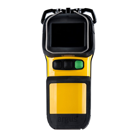
Page 7: Operation And Use
OPERATION AND USE System Configuration (Camera Rear) Mi-TIC E Mi-TIC S 1. 2.7” LCD Display 1. 3.5” LCD Display 2. Display Bumper 2. Display Bumper 3. Pocket Clip (removable) 3. Pocket Clip (removable) 4. Docking latch 4. Docking latch 5. Battery 5. -
Page 8: System Configuration (Charger Front)
System Configuration (Charger Front) Docking bay 2 (spare battery) 5. Camera latching mechanism Docking bay 1 (camera with battery) 6. USB port (front) Camera eject mechanism 7. Charging status LEDs Camera release button 8. Front cover (removable) Up to six chargers can be powered in a “daisy chain” configuration. Connections should be made via the green power connectors located underneath the removable front cover. -
Page 9: Display
3.5 Display 1. Colour reference bar Image Capture 2. Spot Temperature Target Heat Seeker Marker* 3. Spot Temperature Reading Cold Seeker Marker* 4. Battery Bar Video Capture 5. Application mode Zoom 6. Operational Format Low Sensitivity Mode 7. Compass* Time and Date 8. -
Page 10: Getting Started
3.6 Getting Started The packing case contains the following items (see Quick Start Guide): Camera with pocket clip fitted • Charger Station • • Quick Start Guide • Two rechargeable battery packs USB Lead • • Retractable lanyard Power Supply Kit: •... -
Page 11: Camera Features
Camera Features 3.7.1 Application Modes ® The argus Mi-TIC E and Mi-TIC S have up to seven application modes: FIRE Used for attack and rescue in large, fully developed fires. A white-hot grey and colour scale, with the brightness expanded to cover the dynamic range of the scene. - Page 12 OVERHAUL Used for checking for hot spots after the fire is out. A white-hot grey scale, expanded to cover the dynamic range of the scene. Red colourisation is added to the hottest 2% scene, regardless of absolute temperature. Yellow colourisation is added to the next hottest 5% of the scene regardless of absolute temperature.
- Page 13 SIZE UP Used to easily locate the fire from outside of a structure. A white-hot grey scale, expanded to cover the dynamic range of the scene. This mode features a limited dynamic range of 250°C / 480°F so that yellow colourisation comes in earlier at 80°C / 180°F.
- Page 14 INSPECTION Used for predictive maintenance to check equipment and buildings to help prevent fire. A white hot, full colour scale (black, blue, purple, orange, yellow through to white), expanded to cover the dynamic range of the scene. The colour reference bar has no temperature scale. Image detail remains visible throughout the range by changes in brightness and colour saturation.
- Page 15 WHITE HOT Used for general search, with no colourisation. A white-hot grey scale, expanded to cover the dynamic range of the scene. The colour reference bar has no temperature scale. Image detail remains visible throughout the range by changes in brightness. Range °C Range °F Dynamic...
- Page 16 MISSING PERSONS Used for searching for people in landscapes, buildings or traffic accident scenes. A blue-hot grey scale, expanded to cover a limited dynamic of the scene between -40°C - 80°C (-40°F - 180°F) The colour reference bar has no temperature scale. Image detail remains visible throughout the range by changes in brightness and colour saturation.
- Page 17 BLACK HOT (only available on -C variant) Used for general search A black-hot grey scale, expanded to cover the dynamic range of the scene. The colour reference bar has no temperature scale. Image detail remains visible throughout the range by changes in brightness. Range °C Range °F Dynamic range...
-
Page 18: Direct Temperature Measurement
® range. The Argus Mi-TIC will switch to the optimum level of sensitivity automatically and will indicate when it is not in high sensitivity mode by displaying a green coloured solid triangle symbol at the top left of the display. -
Page 19: Zoom
• Low Sensitivity Mode ® The Argus Mi-TIC will automatically switch to Low Sensitivity mode when higher temperatures have been detected, a small green triangle symbol will be displayed in the top left corner to indicate this. The image produced will still be clear with lots of detail, although some additional noise will be visible in the cooler areas of the scene. -
Page 20: Video Capture
The image capture symbol appears for a short time on the left-hand side of the LCD display. The number of the images remaining will be indicated on the display. Images are stored on the camera in compressed .jpg format. This function is part of the TI BASIC PLUS operational format (see 3.9) 3.7.7 Video Capture Videos are stored in the camera’s embedded storage in Motion... -
Page 21: Video Playback
3.7.10 Video Playback Video playback allows fire-fighters to review video at the scene. Once in video playback mode, videos will play automatically and the following button functions will apply Left button short press Restart current video Left button double press Previous video (within 3 seconds) Left button hold... -
Page 22: Electronic Compass
3.7.12 Electronic Compass An electronic compass provides improved situational awareness by displaying N, NE, E, SE, S, SW, W or NW depending on which way the camera is pointing.* *Mi-TIC S only The compass will work within 45 degrees from vertical in both axes. When the camera is tilted past 45degrees, the tilt symbol is displayed instead of the heading. -
Page 23: Heat Seeker And Cold Seeker
3.7.13 Heat Seeker and Cold Seeker The red crosshair immediately indicates the hottest part of the scene. The temperature of the hottest part can be reported.* The blue crosshair immediately indicates the coldest part of the scene. The temperature of the coldest part can be reported.* *Mi-TIC S only The reported temperature can be configured to display either the tracker temperatures or the standard center spot temperature... -
Page 24: Display Warning Graphics
Display Warning Graphics ® The Argus Mi-TIC is equipped with an advanced microprocessor based control and user warning system. In addition to controlling the automatic operation of the camera to ensure the best possible picture at all times, the control system provides graphics on the display to alert the user to certain conditions as follows: 3.8.1... -
Page 25: Nfpa1801 'Ti Basic' And 'Ti Basic-Plus' Operational Formats
Electronic Compass as detailed in section 3.7.9 • Heat Seeker and Cold Seeker as detailed in 3.7.10 • ® Button functions can be changed or removed using the Argus Mi-TIC Configuration Tool detailed in section 6. 3.10 Operating Notes Interpreting The Image – Relative Temperatures •... - Page 26 Identification of Fire and Hotspots • The camera will represent zones of very high temperature as white or red within the picture. When sufficient heat has been detected, e.g. a large area of fire, the camera will automatically enter low sensitivity mode. This will extend the dynamic range of the camera and allow the image of surrounding objects to remain clearly visible.
- Page 27 Heat Layers in Closed Spaces • In a major fire, a layer of hot gases may build up in the upper region of the closed space. Attempting to use the camera in this hot layer will cause the image to become featureless.
-
Page 28: Batteries And Charging
® ® The Argus Mi-TIC camera is supplied with two Argus Mi-TIC Lithium Iron Phosphate Rechargeable Battery Packs (ARG_MI_BLPYN or ARG_MI_BLPSN). These battery type power the camera for over 2 hours from a full charge regardless of operating mode (e.g. video recording) and camera type. -
Page 29: Battery Life Indicator
When the battery symbol starts to flash, the time remaining will typically be 10 - 15 minutes. ® 4.3 Argus Mi-TIC Charger Station Fixed / Vehicle Installation ® The Argus Mi-TIC Charger Station can be mounted on any surface either horizontal or vertically using the universal mounting plate and mounting screws supplied. - Page 30 Using the universal mounting bracket as a template, mark out the drill-hole positions and drill holes. Using suitable fixings, attach the mounting plate to the chosen horizontal surface. Up to six (6) charger stations can be powered in a “daisy chain” configuration. The mounting plates are designed so they can be mounted next to each other as shown below.
-
Page 31: Vertical Mounting
Hook the charger station on to the universal mounting plate. Fasten the charger station to the universal mounting plate with the M4 x 30 mounting screws using the 3 mm hex key as shown. Replace the front panel on the charger station. 4.3.2 Vertical Mounting Follow the same procedure as for a horizontal mounting, but on a vertical surface. -
Page 32: Connecting The Camera To A Pc
2. Using 18 AWG wire or thicker, connect the terminals as shown overleaf, ensuring that the positive (+ve) terminals are connected together and that the negative (-ve) terminals are connected together. 3. Replace the front panels on the charger stations. Note: Do not use the rear power connector when in the ‘daisy-chain’... -
Page 33: How To Copy The Memory Card Contents To A Pc
It is recommended to use MS Paint to create the image file. Turn the camera on. Connect the camera to the computer via the Argus® Mi-TIC Charger Station and the supplied USB lead. The computer should recognise the memory card as a ‘Mass Storage Device’ and open a file explorer window. -
Page 34: Diagnostic File
Configuration tool Mi-TicManual.pdf Manual Diagnostic File The diagnostic file can be found in the top level ‘ARGUS TIC’ directory on the memory card. The name of the file is: MInnnnnn.txt (nnnnnn is the camera serial number) The diagnostic file contains information about the camera which may be useful to Avon Protection in diagnosing any camera faults. -
Page 35: Configuration Software
• Running the Configuration Tool ® ® To run the software, connect the argus Mi-TIC to your computer using the argus Mi-TIC Charger Station and the supplied USB cable. The camera is recognised as a removable disk. Navigate to the removable disk and open it. -
Page 36: Setting The Temperature Units
Setting the Temperature Units Select either C or F, then click the ‘Save Changes’ button circled in red below. Eject the camera from the charger dock. Do not switch the camera off and back on again. The new settings will be enabled. ©... -
Page 37: Setting The Time And Date Format
6.3 Setting the Time and Date Format Select either GB or US, then click the ‘Save Changes’ button. Eject the camera from the charger dock. Do not switch the camera off and back on again. The new settings will be enabled. -
Page 38: Black Box" Video Recording
6.5 “Black Box” Video Recording Check the “Black Box Video Recording” box, then click the ‘Save Changes’ button. Eject the camera from the charger dock. Do not switch the camera off and back on again. The new settings will be enabled. Note: When “Black box”... -
Page 39: Heat Seeker And Cold Seeker
6.7 Heat Seeker and Cold Seeker Check the “Heat Seeker” box, “Cold Seeker” box or “Heat and Cold Seeker” box to enable trackers. Check the Tracker Temperature box or Spot temperature box, then click the ‘Save Changes’ button. Eject the camera from the charger dock. Do not switch the camera off and back on again. -
Page 40: Camera Function Button Set-Up
6.9 Camera Function Button Set-up The following camera functions can be assigned to either of the two function buttons. Functions can be activated by either a short press (less than one second), or a long press (three seconds). • Zoom Cycle through selected Application Modes (Fire, Overhaul, Size Up, Inspection, •... -
Page 41: Restart
6.10 Restart If the Configuration Tool cannot identify the camera, remove the camera from the docking station and restart the camera. This will update the camera identification. © Avon Protection DAS775571AA Version 9, December 2015 GR 13313 CR121804... -
Page 42: Cleaning, Maintenance And Replaceable Parts
Users should therefore expect to replace the batteries during the camera lifecycle. There are very few other ‘lifed’ components in the argus® Mi-TIC camera and repair / replacement of these will be offered via Avon Protection or an authorised repair centre subject to component availability. -
Page 43: Replaceable Parts
P7030NS Argus Neck Strap P7030SC Argus Soft Carry Case THERE ARE NO OTHER USER SERVICEABLE PARTS. If any damage beyond these parts occurs, return the camera to Avon Protection or an authorised repair centre. Any attempt at repair by unauthorised personnel may cause serious damage and will invalidate the warranty. -
Page 44: Replacing The Germanium Window Assembly
Replacing the Germanium Window Assembly 7.4.1 Removal Using a small flat tool, e.g. a small flat head screwdriver, depress the window release latch and turn the Germanium window assembly clockwise. Note the Germanium window assembly contains a reverse bayonet coupling. ©... -
Page 45: Refitting
7.4.2 Refitting Locate the window assembly on the front of the camera and turn the window assembly anti-clockwise until a click is heard. © Avon Protection DAS775571AA Version 9, December 2015 GR 13313 CR121804... -
Page 46: Specifications
SPECIFICATIONS © Avon Protection DAS775571AA Version 9, December 2015 GR 13313 CR121804... - Page 47 © Avon Protection DAS775571AA Version 9, December 2015 GR 13313 CR121804...
- Page 48 EMEA CUSTOMER SERVICE Avon Protection Hampton Park West Melksham Wiltshire, SN12 6NB T: +44 (0) 1225 896705 F: +44 (0) 1225 896301 E-mail: emeacustomerservice@ avon-protection.com ASIA PACIFIC CUSTOMER SERVICE Avon Protection Hampton Park West Melksham Wiltshire, SN12 6NB T: +44 (0) 1225 896705 F: +44 (0) 1225 896301 E-mail: emeacustomerservice@ avon-protection.com AMERICAS...
Need help?
Do you have a question about the Mi-TICS and is the answer not in the manual?
Questions and answers