Table of Contents
Advertisement
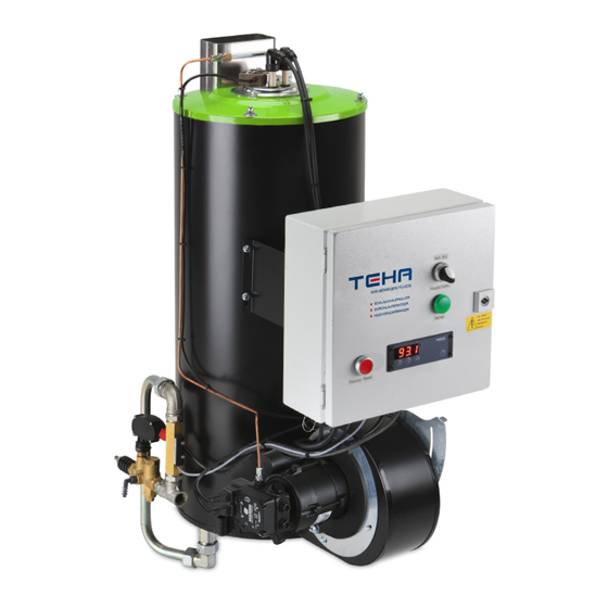
Owners manual for BR1000 ECO PLUS
valid from 01.01.2013
Table of contents
Description ................................................................. 1
Assemblies ................................................................. 1 - 2
Definition and application ........................................... 2
Installation recommendation ...................................... 2 - 4
Service and maintenance ........................................... 4 - 5
Safety advice .............................................................. 5 - 6
Warranty ..................................................................... 6
Exploded view combustion chamber, complete .......... 4
Parts list, combustion chamber, complete ................... 8 - 9
Parts list, mixing device.............................................. 10
Exploded view, mixing device ..................................... 10
Exploded view, switch box .......................................... 11
Parts list, switch box .................................................. 12
View of burner adjustment settings ............................ 13
Dimensioned drawing, combustion chamber ............... 13
Circuit diagram with flame control .............................. 14
Chimney connecting piece .......................................... 15
Enclosure: Trouble shooting guide .............................. 16 - 20
Technical data ............................................................ 20
Digital control ............................................................. 21-31
1. Description
Theodor Henrichs' new boiler technology enables you to achieve less soot discharge at a very high performance level.
The nominal capacity of 90-95kW is well controllable by means of the digital thermostat. If you need high and constant
temperatures, the BR1000 ECO PLUS is what you need.
2. Assemblies
The combustion chambers mainly consist of the following assemblies: (See also exploded view page 7)
Burner Type B90 (See also exploded view page 10)
The BR series of vertical burners have proven themselves over the years and the design is applied unchanged for all types
of combustion chambers. The different capacities are achieved by the fitting of fuel nozzles with different flow rates and
corresponding changes in air flow.
Heating coil (See also exploded view page 7, Pos.37)
An efficient high capacity is achieved by using double wound heating coils. Their tube wall thickness is strongly over
dimensioned, so that normally a long lifetime is guaranteed. Almost all applications can be covered due to the large range
of varieties:
Material:
Dimensions:
Range of pressure:
Casing (See also exploded view page 7, P. 35 + 36)
Between the inner and the outer casing is an integrated ventilator housing building a ring gap.
Through this ring gap the burner is provided with combustion air. The following advantages arise from this method:
a.
The outer casing is cooled.
b.
The combustion air is preheated.
c.
Due to the double casing the construction is very stable and extremely rigid.
Galvanized, powder coated steel sheet and stainless steel 1.4301 are the available materials.
steel, stainless steel 1.4301 and 1.4571
3/8" and 1/2"
up to 500 bar
Page
1
Advertisement
Table of Contents

Summary of Contents for TeHa BR1000 ECO PLUS
-
Page 1: Table Of Contents
Theodor Henrichs’ new boiler technology enables you to achieve less soot discharge at a very high performance level. The nominal capacity of 90-95kW is well controllable by means of the digital thermostat. If you need high and constant temperatures, the BR1000 ECO PLUS is what you need. 2. Assemblies... -
Page 2: Definition And Application
Ventilator motor, ventilator fan and oil pump are the next assembly. (page 7, P. 22, 20 and 24). A solenoid valve controls the oil supply of the burner thermostatically. Normally a two step pump with integrated solenoid valves is installed. The combustion chamber is formed by an extremely heat resistant tube reaching deeply into the flame area. - Page 3 Alternatively outside air suction can be carried out by means of a pipe system. A suitable ventilator joint is available from the TEHA accessories range. The nominal diameter of the tube shall be Ø >=110 mm. In case of danger of frost a motor driven lid is recommended.
-
Page 4: Service And Maintenance
Special attention has to be paid to the fact that the burner ventilator should not suck in its own or foreign exhaust gases. The same applies to dust of all kinds, like for example wheel swarf and lacquer dust in production areas in industry and in workshops.The following are just two problems likely to be caused by excessive dust in the intake air: The dust particles are polluting the baffle plate, leading to malfunction of the burner. -
Page 5: Safety Advice
5.2.4 Adjustment of the regulating devices, 5.2, Pos. 1–3, leads to the following changes: 1) more air: better smoke appearance lower CO2 – value higher exhaust gas temperature worse ignition behaviour 2) pulling out of the nozzle tube: better smoke appearance lower CO2 –... -
Page 6: Warranty
Stationary installations (see also 4.1.2!) always have to be equipped with a flame control system. Otherwise the flame might stop or start off unnoticed. If the flame stops, unburned oil may continue to be injected and the leaking oil may cause severe damage. - Page 7 BR1000 ECO PLUS, oil heated, since 01.01.2013...
-
Page 8: Parts List, Combustion Chamber, Complete
Inner lid, chimney, flame tube, insulating plate, diffusor 260mm E10400763 Insulating plate for inner tube Drm 181 (belongs to 7) B10400096-4 Inner tube, BR1000 ECO PLUS 295mm (belongs to 7) B10400201 Eyebolt, complete.8 with countersunk bolt., washer, nut E10400252-2 Eyebolt M6x50, galvanised... - Page 9 E10400057 Spacer E10400166 Oxydceramic disk, Ø290 x 8, 2 holes B10400204-ECO Outer casing BR1000 ECO PLUS, galvanised, powder coated, RAL9005 B1040016301 Inner casing BR1000, stainless steel B10400145-1 Heating coil HZ100, steel, 3/8“, 300bar, for BR1000 Heating coils for further nominal Ø, materials and operating pressures upon request...
-
Page 10: Parts List, Mixing Device
List of parts, mixing device BR1000 ECO PLUS Pos. Code-No. Pieces Description B10400006 Electrode holder, half B10400087 Centering device, since 1992 E10400570-2 Oil nozzle 2,25/60°H E10400118-1 Nozzle holder with thread M8, hexagon, brass E10400464-2 CIM Igniting electrode, short. since 2011... -
Page 11: Exploded View, Switch Box
Switch box BR1000 ECO PLUS, oil heated Drawing No.: Schaltkasten_KPL300x300... -
Page 12: Parts List, Switch Box
Parts List, Switch box BR1000 ECO PLUS Pos. Code-No. Pieces Description see Pos 24 Counter nut (belongs to item 24) E10400741 Fastening adaptor M22 A E10460034 Switch link M22 K10 E10850009 Switch box, 150 x 150 x 120 mm E10850021-2 Cable channel NF25, 260 mm see Pos. -
Page 13: View Of Burner Adjustment Settings
Dimensional specifications BR1000 ECO PLUS Heating coil 3/8“ A=126mm, B=99mm Heating coil 1/2“ A=132mm, B=101mm... -
Page 14: Circuit Diagram With Flame Control
Circuit diagram BR1000 ECO PLUS Oil flame control Step 2 Step 1 Pressure switch Reset button Regulating thermostat K2 10 Fault light 95°C switch off temperature 11 Main switch Flow switch K1 Switch relay Temperature limiter M Motor Solenoid valve... -
Page 16: Enclosure: Trouble Shooting Guide
Trouble Shooting Guide - In connection with operation of oil heated combustion chambers. Preface For many years now TEHA combustion chambers have been proven appliances to provide instant hot water, especially for use in cleaning applications. They have distinguished themselves by their trouble free working, long life and their robustness. - Page 17 1. Basic information regarding the misbehavior of combustion chambers. The misbehaviour of combustion chambers becomes noticeable by a few measurable indications most of the times. These are: Exhaust temperatures out of the normal range. (>200°C). Temperature of the outer casing out of the norm range (>60°C). Smoke appearance is bad, cannot be adjusted (>1) Water temperature at the outlet is deviating from the norm.
- Page 18 2.1.3 Checking nozzle function Connect the mixing device to the oil pipe while out of the burner. Pull the spark plug socket off the igniting electrodes. Aim the nozzle into a direction where no damage can be caused. Start the burner and observe the atomizing cone. Does a clean atomizing cone build up? If not, change the nozzle.
- Page 19 Reason: The soot has the effect of an insulator. Only part of the produced energy can be delivered to the water. The exhaust channels are mostly blocked by soot. The combustion chamber is entirely overheated. The inner casing and later the outer casing will burn out, if this condition lasts for any length of time. Remedy: Remove the heating coil and clean it with a high pressure cleaner.
-
Page 20: Technical Data
Remedy: Be careful to avoid the sucking in of exhaust gases and dust particles under all circumstances, take special care during the installation of the combustion chamber. 3.5 The temperature limiting safety device always cuts off. See 3.1 and 3.2! Technical Data BR1000 ECO PLUS Typee BR 1000 Nominal capacity [ KW ]... -
Page 21: Digital Control
Digital Control... - Page 22 93°C 0,1 K 0,1 K 95°C WARNING! Change adjustments just in contact with TEHA!
- Page 25 WARNING! Change adjustments just in contact with TEHA!
- Page 26 WARNING! Change adjustments just in contact with TEHA!
- Page 27 WARNING! Change adjustments just in contact with TEHA!
Need help?
Do you have a question about the BR1000 ECO PLUS and is the answer not in the manual?
Questions and answers