Table of Contents
Advertisement
APRS Voyager (firmware v1.03)
(manual revision 06 February 2017)
BUILT-IN 38.5 DBM / 7 WATT TRANSCEIVER
MIC-E/BASE-91/PLAIN TEXT POSITION REPORTING
BUILT-IN BLUETOOTH INTERFACE
SIMPLE ALIAS-BASED APRS PACKET DIGIPEATER
WEATHER STATION SUPPORT
EXTERNAL TELEMETRY MODULE SUPPORT
DIGITAL THERMOMETER SUPPORT
INPUT VOLTAGE MEASUREMENT
SERIAL CONSOLE FOR ADMINISTRATION
EASY USB-HID PROGRAMMING
Instruction manual
Configuration software manual
Designer: Mateusz Płociński SQ3PLX
Producer: Microsat
info@microsat.com.pl
1
Advertisement
Table of Contents

Summary of Contents for Microsat APRS Voyager
-
Page 1: Instruction Manual
APRS Voyager (firmware v1.03) (manual revision 06 February 2017) BUILT-IN 38.5 DBM / 7 WATT TRANSCEIVER MIC-E/BASE-91/PLAIN TEXT POSITION REPORTING BUILT-IN BLUETOOTH INTERFACE SIMPLE ALIAS-BASED APRS PACKET DIGIPEATER WEATHER STATION SUPPORT EXTERNAL TELEMETRY MODULE SUPPORT DIGITAL THERMOMETER SUPPORT INPUT VOLTAGE MEASUREMENT... -
Page 2: Table Of Contents
Table of Contents 1. Technical parameters................3 2. Device features..................4 2.1. Built-in 38.5 dbm / 7 watt transceiver............4 2.2. Mic-E/Base-91/Plain text position reporting..........4 2.3. Built-in Bluetooth interface..............4 2.4. Simple alias-based APRS packet digipeater..........4 2.5. Weather station support..............5 2.6. External telemetry module support............5 2.7. -
Page 3: Technical Parameters
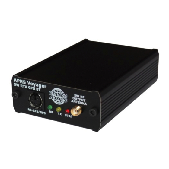
1. Technical parameters Mechanical: Dimensions (without connectors) 100x69x28 mm Weight 150 g Housing material Aluminium Connectors / interfaces: RF connector SMA female Power connector Round 5.5/2.1mm (with plus at center) Telemetry / thermometer connector Terminal with screws (shared) Serial port connector Mini DIN 6-pin female (1 serial port) Bluetooth module HC-05 module, Bluetooth v2.0, Class 2 with... -
Page 4: Device Features
SmartBeaconing position via APRS Voyager. GPS passthrough – if you have a GPS receiver connected to APRS Voyager RS-232 • serial port, then you can forward NMEA stream to any other device using Bluetooth interface. -
Page 5: Weather Station Support
2.5. Weather station support APRS Voyager allows you to receive weather data from compatible weather stations over RS-232 serial interface. Currently supported stations are: LaCrosse/Technoline WS-2300, • LaCrosse/Technoline WS-2350, • Peet Bros Ultimeter 100, • Peet Bros Ultimeter 800, •... -
Page 6: Connectors And Device Status Leds
RF transistors of every kind of transmitters are sensitive for proper antenna match and can get damaged when working in unmatched conditions! APRS Voyager incorporates only one RS-232 serial interface (contrary to PLXTracker or PLXDigi), located on „RS-232 port 2” pins (port 1 is internally occupied by Bluetooth interface). -
Page 7: Rear Panel
3.2. Rear panel On rear panel of the device there is a shared RS-485 / thermometer connector and a round power 5.5/2.1mm connector. Connectors: 4-pin terminal with screws – as shown on the image, you can connect a RS-485 • bus using A+ and B- connectors, or DS18B20-type digital thermometer using V+, GND and DATA connectors (V+ is a weak 5V output for thermometer powering), mini USB - a mini USB socket, used to connect to a computer for configuration,... -
Page 8: Rs-485 / Thermometer Connector
For RS-485 connection please connect RS-485 A+ of APRS Voyager to RS-485 A+ of the module and RS-485 B- of APRS Voyager to RS-485 B- of the module. Both APRS Voyager and telemetry module must share the same ground potential (should be powered from the same power source or at least share the ground wire). -
Page 9: Serial Port Connector
5. Serial port connector In APRS Voyager the MINI DIN 6pin female connector is used for single RS-232 serial port and 5V voltage output. MINI DIN 6pin connector pins description: Pin 6 – not used • Pin 4 – RS-232 Port 2 TXD, •... -
Page 10: Connecting The Weather Station
GND connection and both positive and negative 5V voltages are necessary for interfacing. To connect WS-2300 or WS-2350 station to APRS Voyager you will need to use: - “CAB02B - PLXTracker Blue/TRX1W/APRS Voyager serial interface cable (for WS-23XX)” Schematic for this cable is available on our webpage. -
Page 11: Connecting To Pc
To connect to your computer, follow these steps: Disconnect APRS Voyager DB-9 cable, device should be unpowered, • Connect the USB cable from your computer to APRS Voyager, Red LED should start • to blink (device is now powered from USB), Now you can use APRS Voyager Configurator for device configuration read/write •... -
Page 12: Description Of Configuration Software
Voyager Configurator window to a file on your PC's disk drive. Similarly with “Read from file” button you can import configuration from a file to your APRS Voyager Configurator application. These functions can be used to save your device's configuration and to... -
Page 13: Radio Tab
8.5. Radio Tab “Callsign” – the callsign of your station with SSID extension. This field can be up • to 6 characters long. The default SSID is 0 and allowed SSID's are between 0 and “Latitude” - north-south static position of your radio station (not used if you are •... -
Page 14: Position Reports Tab
“Channel busy detect” - this option selects if channel busy is detected by input • signal amplitude (“analog signal level”) or with proper packet start detection (“digital detect”). The second option allows to work with open-squelch on the radio, but it can lead to some packet collisions. The first option is default and should be used in most cases, “Consecutive packet send”... - Page 15 if your speed is 10 km/h, packet will be sent immediately if turn_threshold = 27 + 410/10 = 68 degrees. If your speed is 80 km/h, packet will be sent immediately if turn_threshold = 27 + 410/80 = 32 degrees. Now we see that packets will be sent with lower heading changes for fast speed and with higher heading changes for low speeds.
-
Page 16: Digipeater Tab
8.7. Digipeater Tab Digipeater Tab contains several options for simple alias-based digipeater feature of APRS Voyager. 8.7.1 Digipeater / Common settings Tab “Digipeater on” – Enables or disables a function of RF APRS packets digipeating, • “Duplicate checking (s)” – Time in seconds after which the next packet will be •... -
Page 17: Digipeater / Simple Aliases Tab
“Alias”, “SSID” - if packet path contains this string and SSID, it will be • digipeated, “Traceable” – if Yes, APRS Voyager will add its own callsign to the path, if No, it • will not do that, “Enable if” – Disables (Never) or enables (always) current row of digipeater •... -
Page 18: Beacons Tab
“Dest” – destination field of a beacon packet. It would be the best to leave it • default which will allow your device to be recognized as APRS Voyager (and added to working stations callsign list on my webpage), “Path 1”, „Path 2” – APRS path, if you leave these fields empty, beacon will be •... -
Page 19: Telemetry Reports Tab
PLXTracker U=<volt>V – beacon information field, <volt> will be replaced with • input voltage reading. As you can see in the above example, APRS Voyager allows to use some special strings, which are automatically replaced with corresponding values: <statlat> - inserts latitude defined on "Radio" Tab. -
Page 20: Telemetry Reports / Report Settings
8.9.1. Telemetry reports / Report settings “Telemetry parameters” – this group of fields defines settings of PARM, UNIT, • EQNS, and BITS parameter packets which describe the telemetry data sent by the device, “Dest” – destination field of a telemetry parameters packet. •... -
Page 21: Telemetry Reports / Analog Channels
messages will be sent, 8.9.2. Telemetry reports / Analog channels This Tab defines 5 analog channels available in APRS telemetry reports. You can select many different sources for channels data, including external WXTelemetry module data (M), other external devices data (E) and device internal data (I). “Name”... -
Page 22: Telemetry Reports / Digital Channels
(including web services like aprs.fi) will not be able do decode your reports properly. 8.9.4. Telemetry reports / WXBits outputs This Tab defines what should be the default states for WXBits output channels. After power-up APRS Voyager will constantly try to set outputs to the defined states, unless changed by the user. -
Page 23: Weather Reports Tab
8.10. Weather reports Tab This Tab contains all settings related to weather station reports. If you are not going to use weather station, you can leave it unchanged. -
Page 24: External Interfaces Tab
• „RS-232 port 2” - selection of RS-232 port function. • APRS Voyager incorporates only one RS-232 serial interface (contrary to PLXTracker or PLXDigi), located on „RS-232 port 2” pins (port 1 is internally occupied by Bluetooth interface). If you wish to use a weather station, serial console, etc., you will need a different set of... -
Page 25: External Interfaces / Bluetooth
8.11.2. External interfaces / Bluetooth „Bluetooth device name” - Bluetooth name which will be displayed on your • laptop/smartphone/tablet when searching for nearby Bluetooth devices, „Bluetooth password” - Bluetooth password which needs to be entered while • pairing with APRS Voyager Bluetooth interface. -
Page 26: External Interfaces / Rs-485 Port
8.11.3. External interfaces / RS-485 port „RS-485 port” - selects between telemetry modules or digital thermometer • connected to RS-485 bus, “WXTelemetry module (analog)” - enables or disables WXTelemetry module • support, “WXBits module (digital)” - enables or disables WXBits module support, •... -
Page 27: External Interfaces / Weather Station
8.11.4. External interfaces / Weather station “Weather station” - selection of weather station model connected to APRS • Voyager serial port. 8.11.5. External interfaces / Serial console... -
Page 28: External Interfaces / Gps Receiver
„Serial console baudrate” - selection of serial console communication baudrate, • „Console debug messages” - enables or disables various debug messages printed • via serial console. 8.11.6. External interfaces / GPS receiver “GPS module baudrate” - selection of GPS receiver communication baudrate. •... -
Page 29: External Interfaces / Kiss
8.11.7. External interfaces / KISS “KISS baudrate” - KISS packet communication baudrate setting, • “KISS direction” - selects KISS direction: • “RF->serial” - only output of packets received from RF, • “both” - output of packets received from RF and forwading of packets from •... -
Page 30: Test Tone
8.12. Test tone This Tab allows to enable test tone generation in APRS Voyager. When test tone is enabled, device will not send and receive any packets. Alternatively it will send a constant test pattern with 50% duty cycle in 20 seconds interval (10 seconds on, 10 seconds off). -
Page 31: Bluetooth Connection With Aprsdroid
9. Bluetooth connection with APRSDroid In this chapter I will show you how to pair APRS Voyager Bluetooth interface with APRSDroid application running on a smartphone. My testing platform is Samsung Galaxy Grand Neo GT-i9060 hosting Android Kitkat 4.4.4. After running APRSDroid we need to get into application preferences. To do it we need to press on three dots in upper-right corner of the screen. - Page 32 Preferences menu. Now click on „Bluetooth settings” option. Enable Bluetooth if necessary and you should see a list of available Bluetooth devices. With APRS Voyager you will see „APRSVoyager” name instead of „BT/MICROSAT_0003”.
- Page 33 After successful pairing you should see the device as paired: Now get back to Preferences, press on „Connection Preferences” and then on „TNC Bluetooth device” to select your paired device as preferred Bluetooth TNC (again you will see APRSVoyager instead of „BT/MICROSAT_0003”:...
- Page 34 Now you can leave the menu and get back to the main window of APRSDroid application: Press on „Start Tracking” and you should get a confirmation that connection was opened correctly. After some time you should start to see received packets:...
- Page 35 You can also open a map to see received stations plotted on Google Maps: And that is all about connecting your APRS Voyager to APRSDroid. With APRSDroid you can also send and receive messages from other APRS users or use your smartphone's built-in GPS to make a SmartBeaconing tracker without additional external GPS receiver.
Need help?
Do you have a question about the APRS Voyager and is the answer not in the manual?
Questions and answers