Table of Contents
Advertisement
Advertisement
Table of Contents

Summary of Contents for Elcomplus RG-1000e
-
Page 1: User Guide
RG-1000e Remote Gateway User Guide October 2017 R2.0... -
Page 2: Table Of Contents
4 Installation and connection 4.1 Front panel 4.2 Rear panel 4.3 Installation and operation check 5 Examples of using RG-1000e 5.1 Conventional Mode 5.2 Capacity Plus legacy trunking network 5.3 Capacity Plus trunking network with NAI Data (hybrid mode) 5.4 Capacity Plus Muliti-Site trunking network with NAI Data (hybrid mode) 5.5 RG-1000e Repeater mode... -
Page 3: Foreword
Trademarks MOTOROLA SOLUTIONS, the Stylized M logo, MOTOTRBO are registered in the US Patent & Trademark Office. SmartPTT and RG-1000e are the property of Elcomplus LLC. All other product or service names are the property of their respective owners. RG-1000e Remote Gateway... -
Page 4: Revision History
Revision history This table describes the changes to the "RG-1000e Remote Gateway" user guide. Date Version Remarks May, 2017 RG-1000e Remote Gateway, R1.0 Initial version. July, 2017 RG-1000e Remote Gateway, R1.1 Updated release. Updated release. Technical parameters October, 2017 RG-1000e Remote Gateway, R2.0 updated. -
Page 5: Compliance With International Standards
This device complies with EN55032/CISPR32 EN55024/CISPR24. This device complies with DIRECTIVE 2011/65/EU (RoHS 2) This device complies with IEC/EN60950-1. This device complies with TR EAC 020/2011 "Electromagnetic compatibility of technical means", GOST CISPR32- 2015, GOST CISPR 24-2013. RG-1000e Remote Gateway User Guide... -
Page 6: Introduction
MOTOTRBO equipment. It is assumed that users of this guide who will set up the RG-1000e GATEWAY, are familiar with the following: · The principles of building IP networks and radio networks using MOTOTRBO equipment produced by Motorola, ·... -
Page 7: System Purpose
* Note 1: low tier Mototrbo radios DM1400/DM1600, CM200d/CM300d, DEM300/DEM400, XIR M3188/XIR M3688 can not be used with RG-1000e. The 1st generation of Mototrbo radios can not be usedwith with RG-1000e. Note 2: due to Mototrbo firmware limitation middle tier radios DM2600/XPR2500/DEM500/XiR6660 can not setup outgoing All Call. -
Page 8: System Structure
10BASE-T/100BASE-TX Ethernet interface with auto detection of the cable type. For the interaction between the system components, the RG-1000e GATEWAY and radioserver get a static IP address and the TCP and UDP/RTP port numbers, which are used for the radio control commands and audio transmission from the dispatch console. -
Page 9: Technical Specification
2.1 Technical specification 2.1 Technical specification Technical parameters of the RG-1000e GATEWAY are listed in table 1 below. Table 1 RG-1000e GATEWAY technical parameters Network interface parameters Connector RJ45 Standard 10BASE-T (IEEE 802.3) / 100BASE-TX (IEEE 802.3u) Supported TCP/IP protocols UDP, ICMP, IPv4, ARP Transmission rate—10/100 Mbps... -
Page 10: Delivery Set
Interface port USB 1.0 (12 MBps), Device port Software RG-1000e Customer Programming Software (RG-1000e CPS) 2.2 Delivery set The RG-1000e GATEWAY delivery set includes the following components: · RG-1000e GATEWAY —1 pcs., · interface cable* —1 pcs., · FTP5E cable, 6.56 feet (2 m) —1 pcs.,... - Page 11 · USB cable A-miniB, 1 m. —1 pcs. * The 1st interface cable is included in the RG-1000e GATEWAY delivery set by default (for Mototrbo DM 46**e/DM 44**e, XiR M86**i, DGM 8***e/DGM 5***e radios). The 2nd interface cable you need to purchase additionally.
-
Page 12: Operating Principles
To separate the channels on the RG-1000e GATEWAY, each channel is assigned a corresponding IP address and UDP/TCP port number from a range of 1024...65536. When the IP channels of the RG-1000e GATEWAY have equal values of IP address and UDP port, the connection is performed in tandem on idle IP channels. - Page 13 The example of the network configuration for the radioserver and the RG-1000e GATEWAY is shown in the figure below. Fig. 2 Connection of the radioserver to the RG-1000e GATEWAY (single radio) via the local data transm ission netw ork In this example, the radioserver is connected to a single RG-1000e GATEWAY to manage one control station, which is connected to the RADIO interface.
- Page 14 The numbers of these ports are also selected randomly. Then the radioserver starts data exchange with the RG-1000e GATEWAY. To control the connection and the entries in the NAT table, the radioserver and RG-1000e GATEWAY exchange with UDP packets via the corresponding ports every 3 seconds.
- Page 15 Fig. 4 Connection of the radioserver to tw o RG-1000e GATEWAYs via the local data transm ission netw ork The Remote control station 1 settings on the radioserver are used to connect and manage the radio of RG-1000e GATEWAY 1, the Remote control station 2 settings—to connect and manage the radio of RG-1000e GATEWAY When more RG-1000e GATEWAYs are connected to a radioserver, they are configured correspondingly.
- Page 16 Fig. 5 Connection of tw o radioservers (prim ary and redundant) to one RG-1000e GATEWAY A separate IP channel is configured for each radioserver. In this case, the RG-1000e GATEWAY will replicate the data and audio signal, received by the radio, in order to transmit them to each of the radioservers. In case of a primary radioserver failure, all data and control commands will be transmitted via the redundant radioserver.
- Page 17 192.168.1.1 IP address of the internal network interface and the 1.1.1.1 IP address of the external network interface. Router 2, the default gateway of the RG-1000e GATEWAY, has the 192.168.2.1 IP address of the internal network interface and the 2.2.2.2 IP address of the external network interface.
-
Page 18: Installation And Connection
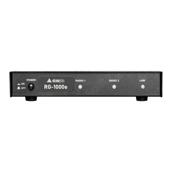
4.1 Front panel 4 Installation and connection 4.1 Front panel The front panel of the RG-1000e GATEWAY is shown in the figure below. Fig. 7 Front panel of the RG-1000e GATEWAY In this figure, the following nomenclature applies: POWER: The power button... -
Page 19: Rear Panel
GND M4 screw , Ground. 4.3 Installation and operation check Before installing the RG-1000e GATEWAY, it is required to perform a visual inspection of the delivery set in order to detect the mechanical damages of the casing or connection elements. Before connecting a radio, it is required to preset the RG-1000e GATEWAY interface. - Page 20 There are some tips w hich help you to deliver pow er properly: · if only one Mototrbo radio is connected to the RG-1000e it is better to get pow er from a connected Mototrbo radio. KM300-DM46 radio connection cable contains necessary w ires for delivering pow er to connected RG-1000e.
- Page 21 2 mm2 section !!! 3. Connect 12-14 VDC power supply to the RG-1000e GATEWAY. Connect the positive lead (+) of your power supply with +V gateway power socket pin, the negative lead (-) of the power supply—with -V gateway power socket pin.
- Page 22 Fig. 10 RG-1000e pow er plug conductors connect-release Note: The GND screw or GND pin (on the pow er socket) of the RG-1000e GATEWAY must be connected to the protective ground of the facility w here it is mounted !!! Note: 15.5VDC is the max imum supply voltage for the RG-1000e GATEWAY.
- Page 23 8. In accordance with the configured operation mode of the RG-1000e GATEWAY interface, connect the required interface cable to the RADIO 1 or 2 connector, which is located on the rear panel of the RG-1000e GATEWAY, and to the corresponding radio connection jack.
-
Page 24: Examples Of Using Rg-1000E
5.1 Conventional Mode 5 Examples of using RG-1000e 5.1 Conventional Mode Fig. 11 Coventional m ode (digital) RG-1000e Remote Gateway User Guide... - Page 25 5.1 Conventional Mode Fig. 12 Conventional Mode (digital + analog) Fig. 13 Conventional Mode Repeater sam ple 1 RG-1000e Remote Gateway User Guide...
- Page 26 5.1 Conventional Mode Fig. 14 Conventional Mode Repeater sam ple 2 Fig. 15 Conventional Mode Repeater sam ple 3 RG-1000e Remote Gateway User Guide...
- Page 27 The figures above show the example of building the system in Conventional Mode between radios. In the given examples the RG-1000e GATEWAY manages two control radio stations, each of them operates on an individual frequency channel and can be programmed to operate both in digital and analog modes. If the dispatchers must be able to operate on more than two frequency channels simultaneously, more RG-1000e GATEWAYs with radio stations can be connected to the radioserver.
-
Page 28: Capacity Plus Legacy Trunking Network
This transmission is performed via the pool (in the given example, 4 units) of the remote control stations connected to several RG-1000e GATEWAYs. The number of the remote control stations depends on the number of required simultaneous calls from the dispatcher/dispatchers. -
Page 29: Capacity Plus Trunking Network With Nai Data (Hybrid Mode)
For Group Calls and Private Calls, the pool of control stations is used. One single control radio station is used for each talkgroup in which the dispatcher/dispatchers must participate. Additionally, one or more radio stations are installed to make Private Calls to the radio subscribers. In the example above three control stations are used to RG-1000e Remote Gateway User Guide... -
Page 30: Capacity Plus Muliti-Site Trunking Network With Nai Data (Hybrid Mode)
You can find more detailed information on the configuration of the control stations in Linked Capacity Plus Hybrid mode in the "MOTOTRBO SYSTEM PLANNER" documentation (“System Topologies” chapter) and the "SmartPTT Radioserver Configurator" software help file. RG-1000e Remote Gateway User Guide... -
Page 31: Rg-1000E Repeater Mode
5.5 RG-1000e Repeater mode 5.5 RG-1000e Repeater mode The RG-1000e GATEWAY may be configured to work in Repeater mode, that allows to create simplest distributed radio networks. In Repeater mode mobile radios and\or repeaters (analog or digital) are connected to the RG- 1000e GATEWAY just using 5 wires: PTT, CSQ, RX Audio, TX Audio and GND. -
Page 32: Storage And Transportation Conditions
6 Storage and transportation conditions The RG-1000e GATEWAY equipment must be stored at the temperatures +41º to +104ºF (+5º to +40ºC), relative humidity less than 80 % at the temperature of +77ºF (+25ºC). The storage site must be free of dust as well as corrosive vapors and gases. -
Page 33: Manufacturer Warranty
1 year from the date of shipping by Elcomplus. Elcomplus, at its option, will at no charge either repair RG-1000e GATEWAY (with new or reconditioned parts), replace it (with a new or reconditioned RG-1000e GATEWAY), or refund the purchase price of the RG-1000e GATEWAY during the warranty period provided it is returned in accordance with the terms of this warranty. -
Page 34: What This Warranty Does Not Cover
+1 786 362 5525, Europe\Africa\Asia Pacific and Middle East phone +7 3822 522 511. 7.4 What this warranty does not cover · Defects or damage resulting from use of the RG-1000e GATEWAY in other than its normal and customary manner. -
Page 35: Appendix I Pin Numberings And Diagrams Of The Interface Cables
Appendix I Pin numberings and diagrams of the interface cables Fig. 20 KM300DM46 cable shem atic RG-1000e Remote Gateway User Guide... - Page 36 Fig. 21 KM300DM26 cable shem atic RG-1000e Remote Gateway User Guide...
-
Page 37: Appendix Ii Clamping Elements
Appendix II Clamping elements The clamping elements of the RG-1000e GATEWAYs and the radio bracket are shown in the figure below. Fig. 22 Clam ping elem ents of the RG-1000e GATEWAYs and the radio bracket The mounting points of the RG-1000e GATEWAY brackets are shown in the figure below.
Need help?
Do you have a question about the RG-1000e and is the answer not in the manual?
Questions and answers