Advertisement
Table of Contents
- 1 The Limiter Module-Parts Description
- 2 The LCD Display
- 3 AC Receptacle for GTIL AC Output
- 4 Clamp Sensor
- 5 Terminal Block- AC Power to Grid
- 6 Wiring Diagram with External Limiter
- 7 Wiring and Connection Procedure
- 8 Connecting Limiter Module DC Output Signal to GTIL
- 9 Connecting Limiter Module to Grid
- 10 Connect the Solar Panel Cable to the GTIL DC Input
- 11 Installation of GTIL with Internal Limiter
- 12 Limiter Setting on the LCD of the Inverter
- Download this manual
Advertisement
Table of Contents

Summary of Contents for Masspower SUN-1000GTIL2-LCD
- Page 1 User Manual of 2 Generation Grid Tie Inverter with Limiter Grid Tie Inverter With Internal&External Limiter (GTIL) 2016-3-1 All rights reserved...
- Page 2 This is the 2 generation GTIL of Masspower.The first generation GTIL must be used with an additional limiter module,we also add an switch button to enable the inverter either can work at limit mode or at normal grid tie mode.
- Page 3 1. On-Grid System Using Standard Grid Tie Inverter 1.1. The Grid Tie inverter converts DC power produced by Solar Panels to AC, connects to the grid and feed all of the power available from the panels to the AC load. 1.2.
- Page 4 On-Grid System Using Grid Tie Inverter With Limiter (GTIL) The Grid Tie Inverter with Limiter delivers only the power needed by the load and prevents delivering excess power hence avoids excess power in going back to the Grid. The heart of the Grid Tie Inverter with Limiter is the Limiter Module (LM). The LM continuously sampled the power needed by the load through the current sensor connected after the Main Circuit Breaker.
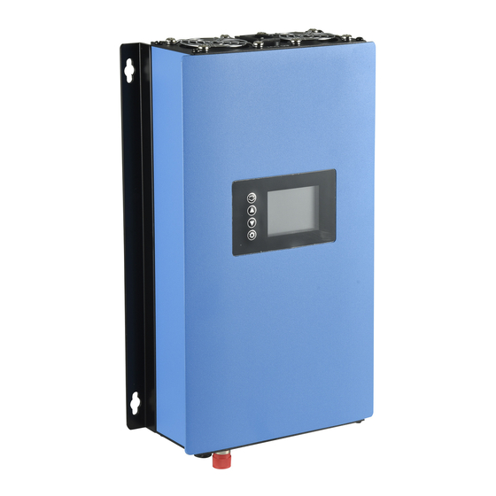
- Page 5 3. The Limiter Module-Parts Description...
- Page 6 3.1. The LCD Display Displays the Utility Power (grid power), Inverter Power (GTIL power), Utility KWH and Inverter KWH. 3.2. AC Receptacle For GTIL AC output Two (2 pcs) - Connects the AC output of GTIL to LM. Can be plug in either receptacle.
- Page 7 WIRING DIAGRAM WITH EXTERNAL LIMITER...
- Page 8 4.1. The installations of the GTIL system are shown above,The ac plug can either connect to the nearby AC socket or plug into the limiter socket,the dc signal cable can reach max 30 meters longth so that you can able to install the inverter far away from the limiter module.The ideal installation is that the limiter install near the GTIL.
- Page 9 breaker dedicated for the GTIL. Make sure the 20A breaker is off while wiring. Do not turn on the breaker! 4.3.3 Connect the DC signal cable from LM to GTIL input. The connectors have threaded screw to securely fasten the connectors plug at both ends of the cable. Also the connector plugs have dent/slot in the plugs body so it can only be connected in one direction or position.
- Page 10 Step4-Connect the solar panel cable to the GTIL DC input 4.3.5. Connect the Solar panel output to the DC power input of GTIL. Make sure the disconnect switch/breaker of solar panel is off. Before connecting the solar panel cable,make sure that the solar panel disconnect switch or DC breaker is off and observe correct polarity when connecting the cable.Failure to follow will cause serious problem with the unit.Pls read the manual booklet of the GTI included in the package for correct wire and...
- Page 11 4.3.8. After initialization, LCD will display Utility Power, which is the actual power or total load in real time. Press the up and down buttons to display the Inverter Power, Utility power, Utility Total KWH and Inverter Total KWH. Inverter Power should read zero initially.
- Page 12 To reset the Utility Total, just press the up button for a few seconds and you will be prompted yes or no to reset. Press up or down button to select either yes or no, and then press SET to reset . To reset Inverter Total, press the down button continuously and you will prompted yes or no also to reset.
- Page 13 4.3.9. Connect the GTIL power output to the LM AC receptacle using the supplied cable. Turn on the disconnect switch/dc breaker of solar panel. The wattmeter in the GTIL should power up and start producing power after a minute or two. 4.3.10 Check the LM display.
- Page 14 remember that for LM module to power-up, need to press Set buttons first in the LM module for the system to run. 5. Installation of GTIL With Internal Limiter 5.1. This installation is not require an additional limiter module,Installation is much easier.Clamp the current sensor cable to the hot wire to measure the current,the internal limiter will auto detect the load power and control the inverter output power,excess power will be well controlled.
- Page 15 Limiter Setting on the LCD of the inverter: The GTIL include three working mode:Work as normal GTI without power limitation.Work under Internal limiter mode and Work under External limiter mode,Pls make your setting on the LCD and save it,details setting operation,pls read the GTI manual.
- Page 16 2. Wattmeter- Max 9999w 3. Terminal Block-Max 20A 4. Receptacle- max 2000w 5. Clamp sensor signal- 5v AC max mA 6. DC signal Cable- 5v DC, ____ max mA Available Masspower GTIL Model 1000W -Model SUN-1000GTIL2-LCD 22-60VDC/45-90VDC,120VAC/230VAC 2000W- Model SUN-2000GTIL2-LCD 45-90VDC/230VAC...
Need help?
Do you have a question about the SUN-1000GTIL2-LCD and is the answer not in the manual?
Questions and answers