Table of Contents
Advertisement
I S W K S e r i e s
H i g h W a l l I n v e r t e r S p l i t
U S E R ' S M A N U A L
E N G L I S H
R e a d t h i s M a n u a l b e f o r e t h e o p e r a t i o n
a n d k e e p i t f o r r e f e r e n c e .
R e a d a l l s a f e t y p r e c a u t i o n s o n t h e
ma n u a l , i mp r o p e r u s e c a n c a u s e
s e r i o u s i n j u r y .
S p e c i f i c a t i o n a n d p e r f o r ma n c e d a t a l i s t e d h e r e i n a r e s u b j e c t t o c h a n g e w i t h o u t n o t i c e
I s a p r o d u c t o f
E n v i r o n m e n t a l T e c h n o l o g i e s L L C .
Advertisement
Table of Contents

Summary of Contents for Streamline ISWK series
- Page 1 I S W K S e r i e s H i g h W a l l I n v e r t e r S p l i t U S E R ’ S M A N U A L E N G L I S H R e a d t h i s M a n u a l b e f o r e t h e o p e r a t i o n a n d k e e p i t f o r r e f e r e n c e .
-
Page 2: Table Of Contents
Content Operation Notices Precautions ......................1 Parts name ......................5 Operation Guide Operation guide....................6 Remote controller ....................7 Buttons on remote controller................8 Maintenance Clean and maintenance ................... 15 Malfunction Malfunction analysis ..................17 Installation Notice Installation drawing ..................20 Installation prepare .................. -
Page 3: Precautions
Precautions WARNING Operation and Maintenance This appliance can be used by children aged of 8 years and above and persons with reduced physical, sensory or mental capabilities or lack of experience and knowledge if they have been given supervision or instruction concerning use of the appliance in a safe way and understand the hazards involved. - Page 4 Precautions WARNING Do not block air outlet or air inlet. It may cause malfunction. Do not spill water on the remote controller, otherwise the remote controller may be broken. When below phenomenon occurs, please turn off air conditioner and disconnect power immediately, and then contact the dealer or qualified professionals for service.
- Page 5 Precautions WARNING Including an circuit break with suitable capacity, please note the following table.Air switch should be included magnet buckle and heating buckle function, it can protect the circuit-short and overload. Don't use unqualified power cord. Make sure the power supply matches with the requirement of air conditioner.Unstable power supply or incorrect wiring or malfunction.
- Page 6 Precautions WARNING The appliance must be positioned so that the plug is accessible. All wires of indoor unit and outdoor unit should be connected by a professional. If the length of power connection wire is insufficient, please contact the supplier for a new one. Avoid extending the wire by yourself.
-
Page 7: Parts Name
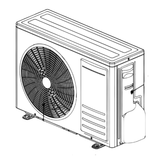
Parts name Indoor unit Panel Air inlet Horizontal louver Filter Air outlet Aux.button Display Temp.indicator Outdoor unit Power indicator Remote controller Air inlet MODE Handle HEALTH SLEEP TURBO I FEEL TEMP CLEAN TIMER TIMER CLOCK QUIET LIGHT Air outlet NOTE: Actual product may be different from above graphics,please refer to actual products. -
Page 8: Operation Guide
Operation guide Installation batteries 1. Press the back side of remote controller marked with " ", as shown in the fig, and then push out the cover of battery box along the arrow direction. 2. Installation two 7# (AAA 1.5V) dry batteries, and make sure the position of "+" polar and "-" polar are correct. -
Page 9: Remote Controller
Remote controller Set fan speed I feel Send signal ● Quiet mode Turbo mode Auto mode Clean mode ● Dual-8 nixietube Cool mode Health function ● Dry mode ECO mode ● Fan mode ● Sleep mode Heat mode Child lock ●... -
Page 10: Buttons On Remote Controller
Buttons on remote controller After connecting the power, the air conditioner will make a sound. Power indicator is ON. After that, you can operate the air conditioner by using remote controller. Under on status, pressing the button on the remote controller, the signal icon " "on the display of remote controller will blink once and the air conditioner will give out a "de"... -
Page 11: Fan Button
Buttons on remote controller FAN button Pressing this button can set fan speed circularly as: auto (AUTO), fan1( ), fan2 ( fan3 ( ) , fan4 ( ), fan5 ( ), stepless speed. AUTO fan1 fan2 fan3 stepless speed fan5 fan4 Note: ●... -
Page 12: Turbo Button
Buttons on remote controller No display ● When selecting " " with remote controller, it’s auto swing. left&right swing louver of air conditioner will swing left&right automatically at the maximum angle. ● When selecting " " with remote controller,it's the fixed position swing. -
Page 13: I Feel Button
Buttons on remote controller I FEEL button Press this button to start I FEEL function and " " will be displayed on the remote controller. After this function is set, the remote controller will send the detected ambient temperature to the indoor unit and the unit will automatically adjust the indoor temperature according to the detected temperature. -
Page 14: Clock Button
Buttons on remote controller CLOCK button Press this button to set clock time. " "and " " icon on remote controller will blink. Press "+" or "-" button within 5s to set clock time. Each pressing of "+" or "-" button, clock time will increase or decrease 1 hour. -
Page 15: Function Introduction For Combination Buttons
Buttons on remote controller QUIET button Press this button to turn on or turn off the QUIET function in cool,heat,auto mode. Note: ● Press "TURBO" or "FAN" button the unit will quit this function. ● This function is no use in fan mode or dry mode. ECO button In cool mode, press "ECO"... - Page 16 Buttons on remote controller The minimum cooling temperature setting In the off mode,pressing "TEMP"and "-" button at the same time,the LCD will display the minimum cooling temperature.The default temperature is 16°C and you can adjust the temperature with "+" or "-" from 16°C to 31°C, 3 seconds later it will return to the standby mode.
-
Page 17: Clean And Maintenance
Clean and maintenance WARNING ■ Turn off the air conditioner and disconnect the power before cleaning the air conditioner to avoid electric shock. ■ Do not wash the air conditioner with water to avoid electric shock. ■ Do not use volatile liquid to clean the air conditioner. Clean surface of indoor unit When the surface of indoor unit is dirty, it is recommended to use a soft dry cloth or wet... - Page 18 Clean and maintenance NOTE: ● The filter should be cleaned every three months. If there is much dust in the operation environment, clean frequency can be increased. ● After removing the filter, do not touch fins to avoid injury. ● Do not use fire or hair dryer to dry the filter to avoid deformation or fire hazard. Checking before use-season 1.
-
Page 19: Malfunction Analysis
Malfunction analysis General phenomenon analysis Please check below items before asking for maintenance. If the malfunction still can't be eliminated,please contact local dealer or qualified professionals. Phenomenon Check items Solution Whether it's interfered severely Pull out the plug. Reinsert the plug (such as static electricity, stable after about 3min, and then turn on voltage)? - Page 20 Malfunction analysis Phenomenon Check items Solution Because indoor air is cooled rapidly. Mist is emitted Indoor temperature and humidity After a while, indoor temperature and from indoor unit’s is high? humidity will be decrease and mist air outlet. will disappear. Temperature can’t be adjusted under Unit is operating under auto auto mode.
-
Page 21: Error Code
Malfunction analysis Error Code When air conditioner status is abnormal, temperature indicator on indoor unit will blink to dispiay corresponding error code. Please refer to below list for identification of error code. Note: Above indicator diagram is only for reference. Please refer to actual product for the actual indicator and position. -
Page 22: Installation Drawing
Installation drawing Space to the wall At least 15cm At least 15cm Space to the wall Drainage pipe... -
Page 23: Installation Prepare
Installation prepare Tools 1 Level meter 2 Screw driver 3 Impact drill 4 Drill head 5 Pipe expander 6 Torque wrench 7 Open-end wrench 8 Pipe cutter 9 Leakage detector 10 Vacuum pump 11 Pressure meter 12 Universal meter 13 Inner hexagon spanner 14 Measuring tape Selection of location Basic requirement... - Page 24 Installation prepare Safety precaution 1. Must follow the electric safety regulations when installing the unit. 2. According to the local safety regulations, use qualified power supply circuit and circuit break. 3. Make sure the power supply matches with the requirement of air conditioner. Unstable power supply or incorrect wiring or malfunction.
-
Page 25: Installation Of Indoor Unit
Installation of indoor unit Step 1: Choosing installation location Recommend the installation location to the client and then confirm it with the client. Step 2: Install wall-mounting frame 1. Hang the wall-mounting frame on the wall; adjust it in horizontal position with the level meter and then point out the screw fixing holes on the wall . - Page 26 Installation of indoor unit 2. Open a piping hole with the diameter of Φ55/Φ70 on the selected outlet pipe position. In order to drain smoothly, slant the piping hole on the wall slightly downward to the outdoor side with the gradient of 5-10°. Note: Indoor Outdoor...
- Page 27 Installation of indoor unit Step 6: Install drain hose 1. Connect the drain hose to the outlet pipe of indoor unit. 2. Bind the joint with tape. drain hose drain hose outlet pipe tape insulating pipe ● Add insulating pipe in the indoor drain hose in order to prevent condensation. ●...
- Page 28 Installation of indoor unit Step 8: Bind up pipe 1. Bind up the connection pipe, power cord and drain hose with the band. 2. Reserve a certain length of drain hose and power cord for installation when binding them. When binding to a certain degree, separate the indoor power and then separate the drain hose.
-
Page 29: Installation Of Outdoor Unit
Installation of outdoor unit Step 1: Fix the support of outdoor Select it according to the actual installation situation 1. Select installation location according to the house structure. 2. Fix the support of outdoor unit on the selected location with expansion screws. Note: ●... - Page 30 Installation of outdoor unit Step 4: Connect indoor and outdoor pipe 1. Remove the screw on the right handle of 2. Remove the screw cap of valve and aim outdoor unit and then remove the handle. the pipe joint at the bellmouth of pipe. liquid valve gas valve handle...
- Page 31 Installation of outdoor unit Step 6: Neaten the pipes 1. The pipes should be placed along the wall, bent reasonably and hidden possibly. Min.semidiameter of bending the pipe is 10cm. 2. If the outdoor unit is higher than the wall hole, you must set a U-shaped curve in the pipe before pipe goes into the room, in order to prevent rain wall...
- Page 32 Installation of outdoor unit Step 7: Vacuum pumping Use vacuum pump liquid valve piezometer 1. Remove the valve caps on the liquid valve gas valve and gas valve and the nut of refrigerant refrigerant valve cap charging vent. charging vent 2.
-
Page 33: Check After Installation
Check after installation Check according to the following requirement after finishing installation. Items to be checked Possible malfunction Has the unit been installed firmly? The unit may drop, shake or emit noise. Have you done the refrigerant leakage It may cause in sufficient cooling (heating) test? capacity. -
Page 34: Configuration Of Connection Pipe
Configuration of connection pipe 1. Standard length of connection pipe ● 5m, 7.5m, 8m. 2. Min. length of connection pipe is 3m. 3. Max. length of connection pipe and max. high difference. Max length Max length Cooling Max height Cooling Max height of connection of connection... -
Page 35: Pipe Expanding Method
Pipe expanding method Improper pipe expanding is the main cause of refrigerant leakage. Please expand the pipe according to the following steps: A: Cut the pipe E: Expand the port Confirm the pipe length according to the Expand the port with expander. distance of indoor unit and outdoor unit. - Page 36 I S W K I 3 A - I M 1 R 0 6 1 6...
Need help?
Do you have a question about the ISWK series and is the answer not in the manual?
Questions and answers
I have a u1 code on ac