Table of Contents
Advertisement
You can take it with you.
DEALER/INSTALLER:
(1) Provide this Manual to end user.
(2) Physically demonstrate hitching and unhitching
procedures in this Manual to end user.
(3) Have end user demonstrate that he/she
understands procedures.
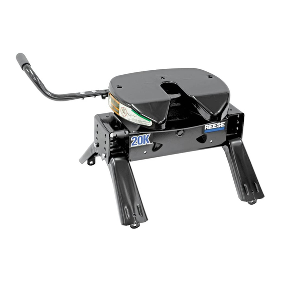
HANDLE
RAMP
CENTER SECTION
Failure to follow all of these instructions may result in death or serious injury
INDEX
8. APPENDIX A (Guidelines for matching hitch, truck, and trailer)
9. APPENDIX B (Guideline for center section orientation)
For Installation Assistance or Technical Help, Call 1-888-521-0510
30081N-2 05/29/14
REV J
INSTRUCTION & OPERATION MANUAL
20K - Fifth Wheel Hitch
SIDE BRACKETS
PCN3723
©2011, 2014 CEQUENT PERFORMANCE PRODUCTS, INC
FOR KITS: 30081, 40261 & 50181
END USER:
(1) Read and follow this Manual every time you use hitch.
(2) Save this Manual and Hitch Warning Hang Tag for future reference.
(3) Pass on copies of Manual and Hitch Warning Hang Tag to any other
user or owner of hitch.
(4) Never remove hitch warning decals as shown on the cover of this
manual. If damaged, contact Cequent Performance Products (1-
800-632-3290) for free replacement.
WARNING:
P. 2
P. 3
P. 6
P. 6
P. 7
P. 9
P. 10
P. 14
JAW TO HOLD
KING PIN
SKID PLATE
HEAD
ASSEMBLY
PRINTED IN MEXICO
Advertisement
Table of Contents

Summary of Contents for Reese 20K
- Page 1 INSTRUCTION & OPERATION MANUAL 20K - Fifth Wheel Hitch You can take it with you. END USER: DEALER/INSTALLER: (1) Read and follow this Manual every time you use hitch. (1) Provide this Manual to end user. (2) Save this Manual and Hitch Warning Hang Tag for future reference.
- Page 2 Fig. B 4. Select 20K Center Section and install on leg aligning holes for hitch height desired. (Lowest position 13" highest 17"). Install four 1/2-13 x 4.5" Hex bolts, (with heads toward inside as shown) and lock nuts. (See Appendix B for center section orientation) 5.
- Page 3 SUPPLEMENT TO 30095N ½” CARRIAGE BOLT (29) INSTALL BOLT IN EITHER POSITION WHICHEVER IS CLOSER TO UNDER BED SUPPORT SPACER (30) SERRATED WASHER (31) LOCK WASHER (32) ½” HEX NUT (33) ADDITIONAL MOUNTING INSTRUCTIONS: Install base rails as instructed in base rail instructions. The instruction below is for the addition of the 2 center bolts for applications using 30095.
- Page 4 GUIDELINES FOR MATCHING HITCH TRUCK AND TRAILER If preparing to tow a 5th wheel trailer which you have not rating checked previously, please consult Appendix A of 5th Wheel Kit assembly instructions. BEFORE EACH TRIP: 1. Lubricate skid plate surface of the hitch and pivot pin grease fitting (see Figure on cover of Manual) with automotive type chassis grease or use a plastic lube plate to provide a lubricated surface.
- Page 5 HITCHING PROCEDURE: IMPORTANT: YOU ARE RESPONSIBLE FOR SAFE HITCHING AND UNHITCHING OPERATIONS. DO NOT RELY ON OTHERS TO PERFORM THESE DUTIES. YOU MUST PERSONALLY MAKE SURE THE FOLLOWING STEPS ARE PERFORMED IN THE FOLLOWING ORDER! WARNING: FAILURE TO FOLLOW THESE INSTRUCTIONS MAY RESULT IN DEATH OR SERIOUS INJURY. 1.
- Page 6 6. With all trailer wheels still firmly blocked, landing gear still resting on firm ground and supporting trailer weight, and truck stationary and in park with emergency brake on: visually check that bottom of pin box is resting on top of the hitch.
- Page 7 WARNING: Do not attempt to hitch by using trailer jacks to lower trailer and king pin. This could result in king pin coming to rest on top of skid plate instead of within hitch opening where jaws are located. King pin could slide off hitch and trailer could drop, resulting in death or serious injury (see Figure 9).
- Page 8 UNHITCHING PROCEDURE: PERFORM THE FOLLOWING IN THIS ORDER: 1. Make sure truck is in park with emergency brake on. 2. Place blocks firmly against front and rear of each trailer wheel to prevent any possible forward or rearward motion. 3. Using trailer jacks, lower trailer landing gear following the directions in the Trailer Manual until feet of landing gear are resting on firm ground.
- Page 9 Figure 11 REF # QTY. DESCRIPTION REF # DESCRIPTION 18K HEAD ASSEMBLY HANG TAG (P/N 110795) 18K CENTER SECTION BAIL PIN WITH LANYARD (P/N 110896) SIDE BRACKET (P/N 30834) LABEL, PINCH POINT (P/N 110954) RETAIN CLIP (P/N 55515) LABEL, OPERATION WARNING (P/N 110793) ½”...
- Page 10 NOTES LIMITED LIFETIME WARRANTY Part No:_____________________________________ Original Purchase:____________________________ Original Owner:_______________________________ Original Installer:_____________________________ 1. Limited Lifetime Warranty (“Warranty”). Cequent Performance Products, Inc. ("We" or “Us”) warrants to the original consumer purchaser only ("You") that the product will be free from material defects in both material and workmanship, ordinary wear and tear excepted;...
- Page 11 Appendix A GUIDELINES FOR MATCHING HITCH, TRUCK, AND TRAILER 30081N-2 05/29/14 REV J PCN3723 ©2011, 2014 CEQUENT PERFORMANCE PRODUCTS, INC PRINTED IN MEXICO FOR KITS: 30081, 40261 & 50181...
- Page 12 Cequent Performance Products’ Engineering Department. 3. Use only a SAE 2-inch kingpin with your 20K Fifth Wheel Hitch. 4. Approximately 15%-25% of trailer weight should be on hitch (Pin Weight). See Figure 13.
- Page 13 5. Trucks come in many different configurations. Cequent Performance Products’ hitches are designed for use in light trucks such as the Ford F-Series, the Chevy Silverado and the Dodge Ram. Cequent Performance Products recommends the use of long bed (8ft) light trucks for the best combination in truck - trailer turning clearance. Rule of thumb: The distance from the back of the truck cab to the center of the rear truck axle (“X”...
- Page 14 Hitch height determination: With trailer leveled and on level ground measure from the ground to the king pin box, “A” in Figure 17. Secondly measure from the height of the inside of the truck bed, “B” in Figure 17. Dimensions “C” and “D” in Figure 17 can be used to determine the amount of clearance over the side rails, as mentioned in Note 17.
- Page 15 Appendix B GUIDELINE FOR CENTER SECTION ORIENTATION 30081N-2 05/29/14 REV J PCN3723 ©2011, 2014 CEQUENT PERFORMANCE PRODUCTS, INC PRINTED IN MEXICO FOR KITS: 30081, 40261 & 50181...
- Page 16 NOTE: SPRINGS NEED TO BE TURNED AROUND NOTE: SPRINGS IN FROM FACTORY LOCATION FACTORY POSITION FOR REARWARD POSITION SHOWN BELOW. HEAD FRONT OF FRONT OF HEAD VEHICLE VEHICLE 14.5” FROM TOP OF CENTER SECTION OFFSET POSITION TRUCK BED TO TOP OF CENTER SECTION HEAD OFFSET POSITION...
- Page 17 INSTRUCTION MANUAL Kwik Slide FOR USE WITH 30048 Cequent Towing Products PLYMOUTH, MI DEALER/INSTALLER: (1) Provide this Manual to end user. (2) Physically demonstrate sliding procedures in this Manual to end user. (3) Have end user demonstrate that he/she understands procedures. END USER: (1) Read and follow this Manual every time you use this Kwik Slide.
- Page 18 WARNING: Failure to follow these instructions may result in death or serious injury! WARNING: Kwik-Slide hitches that are not properly locked can suddenly move and kill you! To avoid death or serious injury: •Never place any part of body in truck bed or between truck and trailer unless the following conditions are met : •Truck is in park with emergency brake on, and •Trailer landing gear is down and resting on firm ground, and...
- Page 19 The 5TH WHEEL KWIK SLIDE provides additional turning clearance for low speed, off-highway maneuvering such as backing a RV trailer into a tight camp site. This is done by sliding the hitch 10 inches rearward of its normal Towing Position (figure 4) to a Maneuvering Position (figure 5). This places the trailer king pin behind the rear truck axle.
- Page 20 INSTALLATION 1. These instructions should be used to mount 5TH WHEEL KWIK-SLIDE. Care and attention to detail will ensure a quick, safe and quality installation. Check parts against figure 1 to become familiar with kit. Leaf spring 2. Before installing 5TH WHEEL KWIK-SLIDE, Aerosol white lithium leaf spring must be greased as shown using grease spray with nozzle...
- Page 21 5. Loosely assemble head support to 5TH WHEEL KWIK-SLIDE at desired height. Hardware will be staggered when assembled. (see figure 10) NOTE: Bottom position may not be used on all hitch models. Use 2 cotter pins provided to trap handle in place as shown. Install indicator pin in handle as shown.
- Page 22 Indicator pin Leaf spring on latch cam keeps latch from disengaging. Hitch can not move rearward with latch engaged. Rearward load forces latch further into slot. Hitch can not move forward due to welded foot (see figures 1, 11 and 12). FRONT OF TOW VEHICLE TOWING POSITION figure 13...
- Page 23 MOVE FROM MANEUVERING TO TOWING POSITION FRONT OF TOW VEHICLE 1. Position truck and trailer in a straight line on a flat, level area. 2. Place truck in “Park” with emergency brake “on”. Indicator pin 3. Block front and back of all trailer wheels. 4.
Need help?
Do you have a question about the 20K and is the answer not in the manual?
Questions and answers