Table of Contents
Advertisement
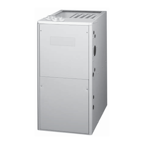
GAS FURNACES
Installation Instructions
Single Stage Condensing Furnaces
*SC Upfl ow/Horizontal Model
WARNING:
• PROPOSITION 65 WARNING: This product
contains chemicals known to the state of
California to cause cancer, birth defects or
other reproductive harm.
• This furnace is not approved for installation
in mobile homes. Installing this furnace in
a mobile home could cause fi re, property
damage, and/or personal injury.
ATTENTION INSTALLERS:
It is your responsibility to know this product better than your
customer. This includes being able to install the product according
to strict safety guidelines and instructing the customer on how to
operate and maintain the equipment for the life of the product.
Safety should always be the deciding factor when installing this
product and using common sense plays an important role as well.
Pay attention to all safety warnings and any other special notes
highlighted in the manual. Improper installation of the furnace
or failure to follow safety warnings could result in serious injury,
death, or property damage.
These instructions are primarily intended to assist qualifi ed
individuals experienced in the proper installation of this appliance.
Some local codes require licensed installation/service personnel
for this type of equipment. Please read all instructions carefully
before starting the installation. Return these instructions to the
customer's package for future reference.
*SL Downfl ow Model
WARNING:
FIRE OR EXPLOSION HAZARD
• Failure to follow safety warnings exactly
could result in serious injury or property
damage.
• Installation and service must be performed
by a qualifi ed installer, service agency or
the gas supplier.
• Do not store or use gasoline or other
fl ammable vapors and liquids in the
vicinity of this or any other appliance.
WHAT TO DO IF YOU SMELL GAS
• Do not try to light any appliance.
• Do not touch any electrical switch; do not
use any phone in your building.
• Leave the building immediately.
• Immediately call your gas supplier from a
neighbors phone. Follow the gas suppliers
instructions.
• If you cannot reach your gas supplier, call
the fi re department.
DO NOT DESTROY.
KEEP IN A SAFE PLACE FOR FUTURE REFERENCE.
92.1% AFUE
Advertisement
Table of Contents

Subscribe to Our Youtube Channel
Related Manuals for Nordyne SC038D-23A


Summary of Contents for Nordyne SC038D-23A
-
Page 1: Installation Instructions
GAS FURNACES 92.1% AFUE Installation Instructions Single Stage Condensing Furnaces *SC Upfl ow/Horizontal Model *SL Downfl ow Model WARNING: WARNING: • PROPOSITION 65 WARNING: This product FIRE OR EXPLOSION HAZARD contains chemicals known to the state of • Failure to follow safety warnings exactly California to cause cancer, birth defects or could result in serious injury or property other reproductive harm. -
Page 2: Table Of Contents
TABLE OF CONTENTS FURNACE INSTALLATION ........14 SAFETY INFORMATION ..........5 General Requirements ..........14 REQUIREMENTS AND CODES ........5 Vent and Inducer Assembly Options .....14 GENERAL INSTRUCTIONS ........6 Inducer Assembly Rotation ........14 Combustion Air Quality ..........6 Pressure Switch Relocation ........15 Operation of Furnace During Construction ....6 Special Instructions for SC038-23A Installation in a Garage ..........7 Furnaces ............15... - Page 3 ELECTRICAL WIRING ..........22 Electrical Information ..........33 Low Voltage Wiring ..........22 Table 6 - Wire length and Voltage Specs ....33 Line Voltage Wiring ..........22 Table 7 - Control Board Fault Codes ....33 Grounding ............23 Figure 24 - Wiring Diagram ........34 Twinning ...............23 Gas Information ............35 START-UP &...
-
Page 5: Safety Information
SAFETY INFORMATION REQUIREMENTS and CODES Safety markings are used frequently throughout this This furnace must be installed in accordance with manual to designate a degree or level of seriousness and these instructions, all applicable local building codes should not be ignored. WARNING indicates a potentially and the current revision of the National Fuel Gas Code hazardous situation that if not avoided, could result in (NFPA54/ANSI Z223.1) or the Natural Gas and Propane... -
Page 6: General Instructions
GENERAL INSTRUCTIONS Operation of Furnace During Construction Combustion Air Quality CAUTION: CAUTION: Failure to follow these instructions will void the factory warranty and may signifi cantly reduce Combustion air must not be drawn from a the life or the performance of the furnace, corrosive atmosphere. -
Page 7: Installation In A Garage
Installation in a Garage COMBUSTION AIR REQUIREMENTS General Information WARNING: WARNING: Do not place combustible material on or against the furnace cabinet or within 6 inches Furnace installation using methods other than of the vent pipe. Do not place combustible those described in the following sections must materials, including gasoline or any other comply with the National Fuel Gas Code (NFGC) -
Page 8: Conventional Furnaces - Confi Ned Spaces
Ventilation Louvers CAUTION: at each end of attic Air Duct must be Exhaust fans, clothes dryers, fi replaces and Vent or at least 1 sq. in. Chimney per 4,000 Btuh of other appliances that force air from the house Attic total input rating. -
Page 9: Alternate Method Of Providing Air From Outside
Alternate Method of Providing Air from Outside: If acceptable under local Codes, it is permitted to Vent or Chimney provide outside air using one opening (See NFGC). Generally, confi ned spaces must have two openings in the space for combustion air. One opening must - - - - - - - - -... -
Page 10: Conventional Furnaces - Unconfi Ned Spaces
Conventional Furnaces - Unconfi ned Spaces Example: An unconfi ned space is an area including all rooms not A space with a water heater rated at 45,000 Btuh separated by doors with a volume greater than 50 cubic input and a furnace rated at 75,000 Btuh requires a feet per 1,000 Btuh of the combined input rates of all volume of 6,000 cubic feet [50 x (45 + 75) = 6,000] to appliances which draw combustion air from that space. -
Page 11: Venting Requirements
VENTING REQUIREMENTS Vent Pipe Material Vent and combustion air pipe and fi ttings must be one of WARNING: the following materials and must conform to the indicated ANSI/ASTM standards. In Canada, all plastic vent pipes and fi ttings including any cement, cleaners, or primers This furnace must not be vented with other must be certifi... -
Page 12: Vent Pipe Installation
Vent Pipe Installation Outdoor Terminations - Horizontal Venting Vent and combustion air intake terminations shall be CAUTION: installed as shown in Figures 6 & 7 (page 13) and in accordance with these instructions: Combustion air must not be drawn from a •... -
Page 13: Vent Freezing Protection
90° Elbow Mounting Kit Faceplate Secured to Wall with Screws 12’ Above Maximum Typical Both Pipes Expected Snow Level (Typ. Both pipes) Combustion Air Inlet Exhaust Vent Left Side Option Inlet Exhaust Figure 9. Vertical Vent Termination Figure 6. Exhaust and Combustion Air Pipe Clearances Vent Freezing Protection When the vent pipe is exposed to temperatures below... -
Page 14: Existing Installations
Existing Installations Before using Table 2, the number of pipes (1-pipe or 2-pipe) When an existing furnace is removed from a vent system connected to the furnace must be known. Find the proper serving other appliances, the existing vent system may furnace style (upfl... -
Page 15: Pressure Switch Relocation
Special Instructions for SC038-23A Furnaces If furnace is to be installed horizontally with airfl ow going from left to right, the pressure switch will need to be moved to the side of the furnace that is not facing STATUS FLAME BLOWER the ground (Figure 12). -
Page 16: Condensate Drain Lines
Condensate Drain Lines both side return air inlets, the bottom panel must not be The methods for draining condensate out of the system removed. If the bottom of the furnace is not being used depend on the confi guration selected. See Figures 25-28 as a return, leave the bottom panel in place. -
Page 17: Bottom Panel Removal
*SC series furnaces are shipped with the bottom panel Bottom Panel installed. If the furnace is installed horizontally, remove the bottom panel from the furnace before attaching the duct system. See Bottom Panel Removal. If the furnace is to be suspended from the ceiling, it will be necessary to use steel straps around each end of the furnace. -
Page 18: Installation On A Concrete Slab
Installation on a concrete slab. CIRCULATING AIR REQUIREMENTS 1. Create an opening in the fl oor according to the dimensions in Figure 16. WARNING: 2. Position the plenum and the furnace as shown in Do not allow combustion products to enter the Figure 17. -
Page 19: Supply Air Connections
60° F (15° C) during operation. If a combination of indoor Side Return Installations and outdoor air is used, the ducts and damper system To attach the return air duct to the left or right side of the must be designed so that the return air supply to the furnace, punch out the four knockouts (Figure 22) from the furnace is equal to the return air supply under normal, preferred side of the furnace. -
Page 20: Gas Supply And Piping
GAS SUPPLY AND PIPING Upflow Models - Right Side Entry All gas piping must be installed in compliance with local codes and utility regulations. Burner Assembly Manifold In the absence of local codes the gas line installation Automatic Gas Valve must comply with the latest edition of the National Fuel (with manual Gas Code (ANSI Z223.1) or (CAN/CGA B149.1 or .2) -
Page 21: Conversion To Lp/Propane
After changing the regulator pressure or the orifi ces, it is WARNING: required that you measure the gas input rate. This may be accomplished in the usual way, by clocking the gas meter The reduction of input rating necessary for high and using the local gas heating value. -
Page 22: Electrical Wiring
ELECTRICAL WIRING The thermostat must not be installed on an outside wall or any other location where its operation may be adversely affected by radiant heat from fi replaces, sunlight, or lighting WARNING: fi xtures, and convective heat from warm air registers or electrical appliances. -
Page 23: Grounding
IMPORTANT NOTE: Proper line voltage polarity must If necessary, press the red button to reset a switch. be maintained in order for the control system to Note: DO NOT install a jumper wire across a operate correctly. Verify the incoming neutral line is switch to defeat its function. -
Page 24: Verifying And Adjusting Temperature Rise
NOTE: Lowering the blower speed will increase the WARNING: temperature rise and a higher blower speed will decrease the temperature rise. Do not attempt to drill the gas orifi ces. Use The furnace is equipped with a multi-speed motor. Heating only factory supplied orifices. -
Page 25: Operating Sequence
OPERATING SEQUENCE • If the W terminal receives a call for heat during continuous fan, the blower will de energize. The operating sequences for the heating, cooling, and fan modes are described below. Refer to the fi eld and furnace •... -
Page 26: Cleaning Of Burners
Cleaning of Burners Heat Exchanger and Burner Maintenance If the burners must be cleaned, follow steps 1-12. See The furnace should operate for many years without soot Figure 34 or 35 (page 46) for component location and buildup in the fl ue passageways, however, the fl ue, vent identifi... -
Page 27: Description Of Components
DESCRIPTION OF COMPONENTS fl ames are not properly drawn into the heat exchanger, the fl ame roll-out switch will close the gas valve and The descriptions below are various functional components initiate the shutdown cycle. that affect the operation and shutting down of this furnace. Some of these components and their locations are shown Gas Valve in Figures 34 and 35. -
Page 28: Furnace Dimensions
FURNACE DIMENSIONS Figure 22. *SC 92.1% High Effi ciency Upfl ow/Horizontal Furnaces... - Page 29 Figure 23. *SL 92.1% High Effi ciency Downfl ow Furnaces...
-
Page 30: Airfl Ow Data
AIRFLOW DATA UPFLOW / HORIZONTAL GAS FURNACES External Static Pressure (Inches Water Column) Heating Model Motor Input Numbers Speed (Btuh) Rise Rise Rise Rise Rise Rise Rise Rise High* 1,245 1,200 1,150 1,100 1,050 Med-High 1,115 1,075 1,030 Med-Low** High* 1,330 1,285 1,230... - Page 31 UPFLOW HORIZONTAL / GAS FURNACES External Static Pressure (Inches Water Column) Heating Model Motor Input Number Speed (Btuh) Rise Rise Rise Rise Rise Rise Rise Rise High* 2,155 2,090 2,015 1,960 1,910 1,835 1,755 1,660 Med-High** 2,015 1,960 1,920 1,860 1,805 1,755 1,695...
- Page 32 DOWNFLOW GAS FURNACES External Static Pressure (Inches Water Column) Heating Model Motor Input Number Speed (Btuh) Rise Rise Rise Rise Rise Rise Rise Rise HIGH* 1,580 1,550 1,520 1,485 1,460 1,425 1,375 1,320 MED-HIGH 1,240 1,230 1,210 1,185 1,165 1,135 1,100 1,045 MED-LOW**...
-
Page 33: Electrical Information
ELECTRICAL INFORMATION Furnace Furnace Cabinet Nominal Maximum Minimum Maximum Minimum Maximum Model Number Input Width Electrical Operating Operating Furnace Wire Fuse or Circuit *SC/*SL (Btuh) (in.) Supply Voltage Voltage Amperes Gauge Breaker Amps** ¼ 038D-23A 38,000 115-60-1 ½ 054D-24B 54,000 115-60-1 10.0 ½... -
Page 34: Figure 24 - Wiring Diagram
HIGH XFMR R C Y G W Figure 24. Wiring Diagram for Upfl ow and Downfl ow Models... -
Page 35: Gas Information
GAS INFORMATION GAS FLOW RATES (CUBIC FEET PER HOUR) TIME FOR CUBIC FEET PER REVOLUTION TIME FOR CUBIC FEET PER REVOLUTION ONE REVOLUTION OF GAS METER ONE REVOLUTION OF GAS METER (SECONDS) (SECONDS) 1,800 3,600 1,500 3,000 12,86 2,571 1,125 2,250 1,000 2,000... -
Page 36: Propane Gas
PROPANE GAS INPUT (BTU) ALTITUDE ABOVE SEA LEVEL 38,000 54,000 72,000 90,000 108,000 120,000 ORIFICE SIZE 0 to 1,999 FT 10.0 10.0 10.0 10.0 10.0 10.0 MANIFOLD PRESSURE ORIFICE SIZE 2,000 to 2,999 FT MANIFOLD PRESSURE ORIFICE SIZE 3,000 to 4,999 FT MANIFOLD PRESSURE ORIFICE SIZE 5,000 to 5,999 FT... - Page 37 NATURAL GAS - HIGH HEATING VALUE INPUT (BTU) ALTITUDE ABOVE SEA LEVEL 38,000 54,000 72,000 90,000 108,000 120,000 ORIFICE SIZE 0 to 1,999 FT MANIFOLD PRESSURE ORIFICE SIZE 2,000 to 2,999 FT MANIFOLD PRESSURE ORIFICE SIZE 3,000 to 3,999 FT MANIFOLD PRESSURE ORIFICE SIZE 4,000 to 4,999 FT...
-
Page 38: Venting Information
VENTING INFORMATION VENT TERMINAL AIR SUPPLY INLET AREA WHERE TERMINAL IS NOT PERMITTED CANADIAN INSTALLATIONS US INSTALLATIONS Direct Vent (2-pipe) & Clearance Location Direct Vent Conventional Vent Conventional Vent (1-pipe) (2-pipe) Furnaces (1-pipe) Furnaces Furnaces Clearance above grade, veranda, porch, deck, balcony, or 12 inches (30cm) 12 inches (30cm) 12 inches (30cm) -
Page 39: Figure 25 - Upfl Ow Options
1 Pipe Upflow See View Option Option Option See View -A- Drain Line See View -B- See View -C- Attached to View -C- (This drain not needed 3/4 x 1/2 if “X” is less than 6”.) Hose Barb Inline VIEW -A- VIEW -B- VIEW -C- Header... -
Page 40: Figure 26 - Horizontal Options - 1 Pipe Furnaces
Horizontal Right - 1 Pipe Option Plug Option See View -D- PVC TEE and Reducer Inlet Air Inlet Drain Line Attached to 3/4 x 1/2 Hose Barb Plug Plug See View -E- See View -D- See View -E- Inline Drain VIEW -F- VIEW -G- VIEW -D-... -
Page 41: Figure 27 - Horizontal Options - 2-Pipe Furnaces
Horizontal Right - 2 Pipe Plug Option Option PVC TEE See View -H- and Reducer Inlet Air Inlet Air Drain Line Attached to 3/4 x 1/2 Plug Plug Hose Barb See View -H- See View -I- See View -I- Inline Drain VIEW -H- VIEW -I-... -
Page 42: Figure 28 - Downfl Ow Options
1 Pipe Downflow Option Option Option View -L- View -M- PVC TEE and Reducer Drain Line Attached to See View -M- See View -L- 3/4 x 1/2 See View -N- Hose Barb VIEW -L- VIEW -M- VIEW -N- Inline Header Box Drain Header Box Drain... -
Page 43: Horizontal Venting
HORIZONTAL VENTING (2-Pipe Shown ) Straps or other Suitable Seal/Caulk Supports at Minimum of Around Pipe 5ft Intervals at Building Combustion Air ° Elbow Exhaust Vent Upward Pitch - 1/4” per Foot 12” Min. 7” Outlet Exhaust Vent First Support Placed Wall as Close to Furnace Maximum Expected... -
Page 44: Figure 30 - Optional Pvc Pipe Installation
**ATTENTION INSTALLERS** When running the 2” PVC pipe out through the top 2” x 3” PVC of the *SC upfl ow furnace, there may be possible Coupling clearance issues when transitioning the PVC pipe from 2” to 3”: • If you have to increase the size of the PVC fl ue from Coil Box 2”... -
Page 45: Accessories
ACCESSORIES The components below are included in the extra parts bag that is supplied with the purchase of your furnace. Depending on your particular installation, some of these components are optional and may not be used. Please refer to the descriptions and accompanying fi gures when installing these items. NOTE: The PVC items shown in Figure 33 are not provided in the extra parts bag. -
Page 46: Location Of Furnace Components
LOCATION OF FURNACE COMPONENTS COMPONENT NAME ITEM Blower Assembly Blower Door Switch Burner Assembly Control Board Finish Flanges Flame Sensor Gas Manifold Gas Valve Igniter Inducer Assembly Limit Switch Main Air Limit Switch Pressure Switch(s) (‘B’, ‘C’, & ‘D’ cabinets only) Roll-Out Switch(s) Transformer Figure 34. -
Page 48: Installation/Performance Checklist
INSTALLATION/PERFORMANCE CHECK LIST ELECTRICAL SYSTEM: INSTALLER NAME: Electrical connections tight? Line voltage polarity correct? CITY _______________ STATE _____________ Supply Voltage: ______________________ VOLTS Has the thermostat been INSTALLATION ADDRESS: calibrated? Is the thermostat level? CITY _______________ STATE _____________ Is the heat anticipator setting correct? UNIT MODEL # GAS SYSTEM:...
Need help?
Do you have a question about the SC038D-23A and is the answer not in the manual?
Questions and answers