
Summary of Contents for NCS NCS-C250C
-
Page 1: Instruction Manual
NCS-C250C INSTRUCTION MANUAL Rev J New Communications Solutions, LLC 5364 Valley Mist Trace Suite 101 Norcross, Georgia 30092 Toll Free Tel. & Fax : 888- 883-5788 Email : support@ncsradio.com Web Site: www.ncsradio.com... -
Page 2: Revision History
(To change microphone setup, see page 9.) (circle Busy Detection mode for each RAD port)) COR: RAD1 RAD2 RAD3 RAD4 Model: ___________________________________ VOX: RAD1 RAD2 RAD3 RAD4 Serial Number: ____________________________ NCS-C250C Instruction Manual Rev J Copyright © 2004-2010 New Communications Solutions, LLC... -
Page 3: Table Of Contents
8.0 Rear Panel Connections................12 9.0 Radio Interface Cables.................14 10.0 Adjustments....................15 11.0 Operating the C250C .................18 12.0 C250C Option Board..................20 13.0 Block Diagram....................24 14.0 Troubleshooting..................25 15.0 Contacting NCS..................26 16.0 C250C Specifications ................27 NCS-C250C Instruction Manual Rev J Copyright © 2004-2010 New Communications Solutions, LLC... -
Page 4: Introduction
All switches are illuminated for low light or night operation and LED indicator brightness is automatically adjusted based on ambient light to provide easy day or night viewing of unit status. Typical Application NCS-C250C Instruction Manual Rev J Copyright © 2004-2010 New Communications Solutions, LLC... -
Page 5: Safety Information
Connect this device only to a DC power source with a voltage output of 12-15 volts and a current capability of at least 2A. NCS-C250C Instruction Manual Rev J Copyright © 2004-2010 New Communications Solutions, LLC... -
Page 6: Accessory Kit
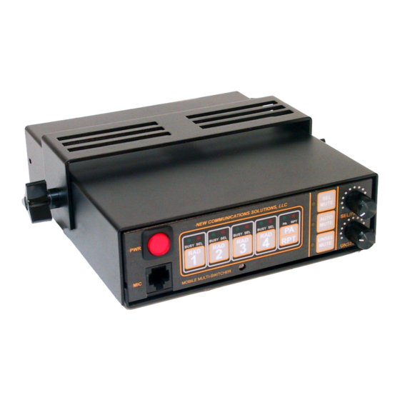
PA/Repeater selection switch with Red RPT and Green PA Indicators, Momentary Mute Function Switches with Yellow Indicators, Momentary Volume Controls for Selected Audio and PA (SEL/PA) and Unselected Audio (UNSEL) Front Panel Microphone Jack , RJ45 Modular NCS-C250C Instruction Manual Rev J Copyright © 2004-2010 New Communications Solutions, LLC... -
Page 7: Radio, Speaker And Microphone Requirements
Some radios use a single line to combine PTT and other control functions. These radios may not be compatible with the PTT circuitry of the C250C . Contact NCS for information on use of these radios. 5.2 Speaker The C250C was designed to drive speakers of 4-8 Ohms nominal impedance. Maximum power output is achieved with 4 Ohm speakers. -
Page 8: Power Supply
MUTE 6.0 Power Supply 6.1 Power Requirements The NCS-C250C will operate with any 9-16 VDC power supply capable of providing at least 2A continuous. 6.2 Power Connection Power is supplied to the pigtail on the rear of the unit. The connector is an Anderson Powerpole PP-15. -
Page 9: Microphone Setup
The function of each pin is programmable using the jumper blocks on the main circuit board. 7.1.1 Microphone Pinouts The RJ45 modular plug pin numbering used on this unit is shown below: NCS-C250C Instruction Manual Rev J Copyright © 2004-2010 New Communications Solutions, LLC... - Page 10 Default Microphone Pin-out Shunt Signal Name ------ Pin 1 ------ Pin 2 ------ Pin 3 Pin 4 MIC Audio Pin 5 Pin 6 ------ Pin 7 ------ Pin 8 NCS-C250C Instruction Manual Rev J Copyright © 2004-2010 New Communications Solutions, LLC...
- Page 11 For microphones with built-in speakers or for headsets, install shunts at the corresponding pin numbers for Selected and/or Unselected Audio on the SEL AUD block (J7) and/or UNSEL AUD block (J6). NCS-C250C Instruction Manual Rev J Copyright © 2004-2010 New Communications Solutions, LLC...
-
Page 12: Rear Panel Connections
To Radio PTT Input Signal Ground Receive From Radio Audio Audio (Speaker) Output Hookswitch and COR Signal Ground require Factory Installed Hookswitch Out to Radio In from Radio Option Board. NCS-C250C Instruction Manual Rev J Copyright © 2004-2010 New Communications Solutions, LLC... - Page 13 SP_S Selected Speaker PA Speaker: Pins 2 and 5. Contacts (18-22 AWG) All speakers may be • AMP 770986-1 Socket connected at the same time. Contacts (22-28 AWG) NCS-C250C Instruction Manual Rev J Copyright © 2004-2010 New Communications Solutions, LLC...
-
Page 14: Radio Interface Cables
PTT signals. It can be fabricated from the documentation supplied in the instruction manual or obtained from NCS. The cable consists of an RJ-45, 8 pin modular connector on one end for mating to the C250C and a radio interface connector on the other end. Un-terminated cables are also available that require the customer to attach the radio interface connector. -
Page 15: Adjustments
Adjustment Radio 4 Radio Transmit Radio 3 Mic Level Level Adjustments Indicator LED Radio 2 Radio 1 Adjustments Inside the C250C FRONT Transmit Adjustments on Bottom of C250C NCS-C250C Instruction Manual Rev J Copyright © 2004-2010 New Communications Solutions, LLC... - Page 16 C250C associated with that radio lights with the lowest level normal received audio. 10.3 User Programmable Functions The NCS-C250C has four user programmable functions. To turn functions on or off, perform the following: 1. Deselect all radios. 2. Press and hold the Mic PTT Button and the UNSEL MUTE button until both the PA (green) and RPT (red) indicators above the PA/RPT button are illuminated.
- Page 17 Function Function Name Button DTMF Mic On/Off RAD1 Sidetone On/Off RAD2 MultiCast On/Off RAD3 Supplemental Thump Filter On/Off RAD4 This completes setup and adjustment of the C250C . NCS-C250C Instruction Manual Rev J Copyright © 2004-2010 New Communications Solutions, LLC...
-
Page 18: Operating The C250C
To mute the Selected radio, momentarily press the SEL MUTE button or the " " button on a DTMF microphone (if enabled). The associated yellow indicator will light and the Selected audio will be silenced. NCS-C250C Instruction Manual Rev J Copyright © 2004-2010 New Communications Solutions, LLC... - Page 19 RPT Mode is on, an audio level that is sufficient to light a radio's Busy indicator will key the PTT for the other Selected radio(s) and retransmit received audio. NCS-C250C Instruction Manual Rev J Copyright © 2004-2010 New Communications Solutions, LLC...
-
Page 20: C250C Option Board
This provides indicators that are not too bright in a dark environment but can still be seen in a bright environment. 12.0 C250C Option Board The NCS-C250C is available with the following features provided by the Factory Installed Option Board: • COR (Carrier Operated Relay) This option causes the Busy Lights and the Repeater function to be controlled by digital Busy signals from the radios. - Page 21 Refer to Section 7 of this Manual for instructions on setting these jumpers. Note that the 200 Ohm jumper position is incorrectly marked on this board. The correct position for 200 Ohms is the two pins next to the label “J10”. Option Board NCS-C250C Instruction Manual Rev J Copyright © 2004-2010 New Communications Solutions, LLC...
- Page 22 NOTE: With the COR Option installed, VOX operation of the Busy Lights and Repeater Function is disabled. Receive input levels should be set using audio voltage measurements to 200mVp-p - 300mVp-p for each radio. NCS-C250C Instruction Manual Rev J Copyright © 2004-2010 New Communications Solutions, LLC...
- Page 23 Off Voltage: < 60 V Add Jumper to Select Microphone Pin Used for On Current: < 200mA Hookswitch. RAD1-RAD4 Modular Radio Connector. Pin 7 is the Hookswitch Signal Line. NCS-C250C Instruction Manual Rev J Copyright © 2004-2010 New Communications Solutions, LLC...
-
Page 24: Block Diagram
Gain Rad4 Rad Mic DTMF Data DTMF Decoder Outputs RS-232 Controller Brightness Mic PTT Input Control Amb Light Front Panel Switches FULL FILENAME PAGE NCS-C250MANUALREVB1.DOC 1 OF 1 NCS-C250C Instruction Manual Rev J Copyright © 2004-2010 New Communications Solutions, LLC... -
Page 25: Troubleshooting
Then check that you have a good ground between all pieces of equipment and that your RF ground is low impedance. NCS-C250C Instruction Manual Rev J Copyright © 2004-20010 New Communications Solutions, LLC... -
Page 26: Contacting Ncs
15.0 Contacting NCS NCS wants you to experience trouble free operation of our equipment. If you have any questions, comments or need technical help, please use the following resources: Go to the web site, www.ncsradio.com. Here you will find the latest instruction manuals, any factory developed modifications and Frequently Asked Questions. -
Page 27: C250C Specifications
Off: > 1 Mohm Max Load Imposed by Radio: Off Voltage: < 60 V On Current: < 200mA COS Sense Selectable Low or High Microphone Pin # Selectable 1-8 NCS-C250C Instruction Manual Rev J Copyright © 2004-20010 New Communications Solutions, LLC... - Page 28 For those products returned that prove to be defective and covered under the warranty, the Customer will bear the cost of shipment for the return of the product to NCS. Collect shipments will not be accepted. NCS will bear the cost of shipment for return of the product to the Customer after repair/replacement. Mode of shipment for return to the Customer will be determined by NCS.
Need help?
Do you have a question about the NCS-C250C and is the answer not in the manual?
Questions and answers