Table of Contents
Advertisement
Advertisement
Table of Contents

Summary of Contents for Enraf Tanksystem HERMetic UTImeter Rtex
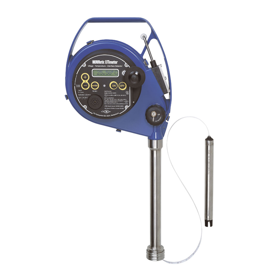
- Page 1 Operation and Service Manual for HERMetic UTImeter Rtex Connectors Q1 and Q2 Portable Electronic Restricted Gauging Device Ullage - Temperature - Interface detector Note : before using the instrument please read this book. 50455/RTEX/0807 UTImeter Rtex...
-
Page 2: Table Of Contents
1. Table of contents ..27 ELECTING THE TEMPERATURE SCALE TABLE OF CONTENTS ........2 ELECTING THE TEMPERATURE RESOLUTION GENERAL INFORMATION ......4 LED ........ 29 CTIVATING THE ..........4 8.5.1 Temporary setting of the LED .... 29 HIPMENT NOTE ........ - Page 3 9.10.3 Checking the UTImeter...... 45 9.11 ..... 46 LLAGE NTERFACE VERIFICATION 9.12 LECTRICAL CHECKING OF THE TAPE .............. 47 ASSEMBLY 9.13 ISUAL INSPECTION FOR DAMAGED OR ............48 MISSING PARTS 9.14 ......48 OATED ALUMINIUM PARTS 9.15 ..... 48 INDING ACTION BECOMING STIFF TROUBLE SHOOTING ......
-
Page 4: General Information
In no event shall Enraf Tanksystem SA be liable 2.4 Warranty for indirect, incidental or consequential loss or damage or failure of any kind connected with the Two (2) years after installation but max. -
Page 5: Certification
MARPOL Resolution MEPC.5(XIII) of 13 June 1980 by When returned to Enraf Tanksystem SA National Maritime Authorities and/or Classification equipment must be contamination-free. If it is Societies. determined that the customers equipment is contaminated, it will be returned to the... - Page 6 Service Request Customer's address: ..........................................................................................................Telephone: ....................E-mail: ..................... Fax: ......................Type of unit or part: ........................................Serial number: ..................Short description of trouble: ................................................................................... Do you want a quotation before repair is started:..yes / no..... Repaired unit has to be returned to the following address: ........................
-
Page 7: Worldwide Service Stations Network
3. Worldwide Service Stations network The updated list can be found on our website www.enraftanksystem.com COUNTRY ADDRESS TELEPHONE/FAX/E-MAIL SWITZERLAND ENRAF TANKSYSTEM SA Tel : +41-26-91 91 500 2, rue de l'Industrie Fax : +41-26-91 91 505 CH-1630 BULLE info@tanksystem.com CANADA... - Page 8 The updated list can be found on our website www.enraftanksystem.com COUNTRY ADDRESS TELEPHONE/FAX/E-MAIL PORTUGAL CONTROLIS Tel : +351-21-2740606 Soc. Com. Equipamentos de Controlo, Fax : +351-21-2740897 Lda. controlis@netc.pt Rua Conceiçao Sameiro Antunes, 26E P-2800 COVA DA PIEDADE RUSSIA NPP "GERDA" Tel : +7-495-7558845 Vilisa Latsisa str.
-
Page 9: Recommendation For Safe Use
4. Recommendation for safe use 1. This Operation and Service Manual is a guide in order to help the user to operate the instrument to our best knowledge. 2. Nevertheless the maker disclaims all responsibility and liability for damage resulting from the use of the equipment regardless of the cause of the damage. -
Page 10: Functions - Key Features
5. Functions - Key Features This HERMetic instrument is a portable multiple functions gauging system that is designed to perform under restricted conditions in a single operation 3 measurements: a) Ullage (outage). Optionally innage is available¹. b) Oil/water Interface level. Tape resolution: 1 mm (1/16 ") Tape accuracy: ±3.2 mm for 30 m (±1/8 "... -
Page 11: Description
6. Description 6.1 General individually Each HERMetic instrument Maintenance is easy because design is modular identified with a 6 digits serial number starting and allows quick exchange of parts. with the letter R, example R10058. This serial number is printed on the identification plate as See also Figure 6-2 to get to know the equipment. - Page 12 Identification plate Crank Display 5 keys pad Reading index Tape cleaner Buzzer Display unit Storage tube SS1 Quick connector Q1 Tape Tape adaptor Sensing probe ULTRA Visc device for innage measurement Figure 6-2 50455/RTEX/0807 UTImeter Rtex...
-
Page 13: Ultra Sensing Probe
6.2 ULTRA sensing probe 6.2.1 Introduction The ULTRA sensing probe consists of a 6.2.2 Ullage detection stainless steel tube terminated by a high- tech plastic head which cannot be The ullage detector consists of two removed from the tube. The sensing piezoceramic plates electronic... -
Page 14: Interface Detection
6.2.3 Interface detection The principle consists of a conductivity the liquid as well and the conductivity measurement between active electrodes associated electronic electrode and a grounded electrode. circuits modulate the coded signal to When the liquid is conductive (as water), generate the intermittent beep. -
Page 15: Ape
6.3 Tape The ETFE (TEFZEL) coated tape provides 3 main index is set up at the zero ullage level, the functions : reading of the tape is identical to the ullage. It holds the sensing probe. It contains 2 wires for transmitting the signal and the power between the display unit and the ... -
Page 16: Ape Protection
6.4 Tape protection The tape protection tube is a mechanical safety prevents closing the valve. When the tape is device which prevents the valve from being closed wound up the protection tube will stay in position as long as the sensing probe is inside the tank. until it is pushed up by the sensing probe. -
Page 17: Reading Index
6.5 Reading index 1300 Zero ullage 1200 Reference level of tank 1100 1000 Liquid level Reaction point Figure 6-9 The tape reading at the height of the reading index If the reading index is positioned below or above of the instrument is indicating the distance the reference level a positive or negative between the reaction point and the reading index. -
Page 18: Tape Cleaner
6.6 Tape cleaner position "DOWN": the wipers are not working, This HERMetic equipment is fitted with a tape the tape is free; cleaner that helps draining the liquid back to the position "UP": the wipers are cleaning the tank when rewinding the tape. It is very easy to tape. -
Page 19: Additional Load (Option)
6.7 Additional Load (option) 6.8 Others An additional load (see Figure 6-2) on the sensing The tape is coiled on a reel which holds also the probe can be provided for one of the following electronic box and the display unit. reasons. -
Page 20: Examples Of Installation Of The Gauging System
7. Examples of installation of the gauging system 7.1 General The gauging system consists of the HERMetic When designing the gauging port and to avoid instrument and the associated HERMetic valve. damaging the tape during rewinding it is advised Two types of connector can be provided as shown to chamfer or to grind all sharp edges (on pipes, on Figure 7-1. -
Page 21: Example Of Installation On A Pipe , 9.6 Connector Q2
7.2 Example of installation on a pipe, connector Q2 SS1 Q1 SS1 Q1 Tank Zero Ullage level Reading Reading index index 460mm 460mm TS supply Thread Customer supply Flange Tank Deck Figure 7-2 Valve designation C.2-SS; C.2-SS-W; C.2-SS-BL; C.2-SS-SEC Bottom connection thread or flange Boring 2”... -
Page 22: Example Of Installation On The Deck , 9.8 Connector Q1
7.3 Example of installation on the deck, connector Q2 Tank Zero Ullage level SS1 Q2 SS2 Q2 Reading Reading index index 474mm 474mm Tank Deck Flange Flange Figure 7-3 Valve designation C.2-SS; C.2-SS-W; C.2-SS-BL; C.2-SS-SEC Bottom connection thread or flange Boring 2”... -
Page 23: Connector Q1
7.4 Example of installation on a pipe, connector Q1 SS1 Q1 SS1 Q1 Tank Zero Ullage level Reading Reading index index 460mm 460mm TS supply Thread Customer supply Flange Tank Deck Figure 7-4 Valve A.1-SS C.1-SS C.1-SS C.1-SS C.2-SS C.2-SS A.2-SS A.2,5-SS A.4-SS... -
Page 24: Connector Q1
7.5 Example of installation on the deck, connector Q1 Tank Zero Ullage level SS1 Q1 SS1 Q1 Reading index Reading index 460 mm 460 mm Tank Deck Thread Flange Figure 7-5 Valve A.1-SS C.1-SS C.1-SS C.1-SS C.2-SS C.2-SS A.2-SS A.2,5-SS A.4-SS designation C.2-SS-W... -
Page 25: Operation
8. Operation 8.1 Basic rules concerning the 5-key control pad Apart from the "ON" / "OFF" keys that are self- pressing "enter" (later on named "E") allows to explanatory, there are 3 other keys that help in enter a specific menu. customising the unit: The small pointer displayed on the left is showing pressing "+"... -
Page 26: Selecting The Language
8.2 Selecting the language English, German or French languages can be selected by following the sequences described in Figure 8-2. UTImeter Ver x.xx Battery ééééé 97% LED menu Init. ********* 25.94°C T. unit Settings Resol. Language English Deutsch Francais Figure 8-2 Switch on the equipment, Wait until the temperature is displayed, Press on "+"... -
Page 27: Selecting The Temperature Scale
8.3 Selecting the temperature scale The temperature can be displayed either in Celsius or Farenheit degrees. Refer to Figure 8-3. UTImeter Ver x.xx Battery ééééé 97% LED menu Init. ********* 25.94°C T. unit > °C °F °C > °F Settings Figure 8-3 Switch on the equipment, Wait until the temperature is displayed,... -
Page 28: Selecting The Temperature Resolution
8.4 Selecting the temperature resolution The temperature reading can be given with 1 or 2 digits after the dot. Select the appropriate resolution as shown on Figure 8-4. UTImeter Ver x.xx Battery ééééé 97% LED menu Init. ********* 25.94°C T. unit Settings Resol. -
Page 29: Activating The Led
8.5 Activating the LED Refer to Figure 8-5. The LED can be activated on 2 modes: one is temporary, it is automatically erased when the unit is switched off, in order to save the battery life; the other is permanent, it will stay even is the unit is switched off. UTImeter Ver x.xx Battery... -
Page 30: Muting The Buzzer
8.6 Muting the buzzer UTImeter Ver x.xx Battery ééééé 97% Init. Buzzer OFF ********* - / medium / 5 min 25.94°C auto Backlight ON Figure 8-6 When in measurement mode it is possible to mute the buzzer. Press on "-", Press on "-"... -
Page 31: Instrument
8.8 Checking the functions before using the instrument Before installing the HERMetic instrument as described in section 8.9, the following tests are recommended to ensure that the instrument is ready to work. 8.8.1 Battery 8.8.3 Ullage Refer to section 9.2 "Checking the battery". Switch on the unit. -
Page 32: Installation Of The Instrument
8.10 Ullage / interface 8.9 Installation of the instrument measurement This HERMetic equipment must be coupled to Install the HERMetic equipment as per 8.9 a certified HERMetic valve. "Installation of the instrument”. Before starting please read c arefully the ... -
Page 33: Reference Height / Innage Measurement
8.11 Reference height / innage final checking. Calculate the free water height by subtracting the index reading to the measurement reference height. If the unit is fitted with the additional load (model Reengage the tape cleaner on the "UP" SS2 Q2, see Figure 8-8) then reference height / position and raise up the sensing probe until innage measurement are possible. -
Page 34: Temperature Measurement
8.12 Temperature measurement Install the HERMetic equipment as per 8.9 "Installation of the instrument”. Open the valve by turning the handle. IMPORTANT NOTE Switch on the unit: a control beep is audible As mentionned in 8.6 "Muting the buzzer" it is easy every 2 seconds. -
Page 35: Care And Maintenance
9. Care and Maintenance 9.1 Care Clean the instrument of any excess of liquid after use. Make sure that the sensing probe is completely stored in the storage tube after use (reading index shall indicate less than 420 mm or 1 ft 5 "). Check the tightness of the reading index screws and if necessary adjust the level, refer to section 9.9. -
Page 36: Checking The Battery
9.2 Checking the battery Please note that in case you have to change the battery, it must be done only in a safe area. Refer to section 9.3 "Battery replacement". 9.2.1 Before starting gauging Switch on the unit. The buzzer tones every 2 seconds if the battery is not too low. The following sequences are displayed as per Figure 9-1, the 4 sequence shows the remaining power of the battery in percentage and as a bar-graph. -
Page 37: During Gauging
9.2.2 During gauging When the unit is already switched on and working, it is always possible to see what power is left with the battery by entering the settings menu: Press on "+" to enter the settings menu, Press on "enter", "LED menu" is displayed, Press on "+";... -
Page 38: Battery Replacement
9.3 Battery replacement Warning : change the battery only in a non hazardous area. Unscrew the 2 screws of the battery holder using the 2,5 mm Hex Allen key which is located on the carrying case. See Figure 9-4. ... -
Page 39: Tape Replacement
9.4 Tape replacement THE REPLACEMENT OF THE TAPE DOES NOT REQUIRE TO RE-CALIBRATE THE TEMPERATURE. Follow the different sequences as described below. The Figure 12-1 : general assembly, list of the main spare parts can also help. 9.4.1 Disconnecting the tape from the sensor Follow the instructions of section 9.5 "Sensing probe replacement". -
Page 40: Disconnecting The Tape From The Reel
9.4.3 Disconnecting the tape from the reel Carry out the functional tests as per 8.8 axle "Checking the functions before using the instrument". Remove the external reel flange (3 screws to If there is any problem, refer to section 10 unscrew with the 2.5 Allen key). -
Page 41: Sensing Probe Replacement
9.5 Sensing probe replacement REPLACEMENT SENSING PROBE DOES REQUIRE CALIBRATE THE TEMPERATURE NOR THE ULLAGE / INTERFACE. 9.5.1 Disconnecting the old sensing probe Unscrew the securing screw with the 1.5 mm Hex Allen key. Pull carefully the adaptor out of the sensing probe tube by turning it slightly left and right. -
Page 42: Tape Wipers Replacement And Removing
9.6 Tape wipers replacement and removing of tape cover The 2 tape wipers can be easily replaced: Check that the tape cleaner is on "DOWN" position. wipers Pull the tape cover out of the frame. Use pliers or a rod to help the clips to get out of the frame (as shown in figure 9.10) ... -
Page 43: Display Unit Replacement
9.8 Verification and certification of 9.7 Display unit replacement tapes THE REPLACEMENT OF THE DISPLAY UNIT The tape has to be periodically inspected for DOES NOT REQUIRE TO RE-CALIBRATE THE breaks, kinks, wear and illegible numbers. TEMPERATURE. As the tape is a cable it might be necessary to check its electrical conformity. -
Page 44: Verification And Adjustment Of The Reading Index
9.9 Verification and adjustment of the reading index To verify or to adjust the reading index, in IMPORTANT NOTE: these adjusting values for particular after having renewed a tape, apply the the reading index are different from the heights following instruction: shown in the section 7 "Examples of installation of if the equipment is fitted with a 2"... -
Page 45: Temperature Verification
9.10 Temperature verification The temperature calibration curve is stored in the sensor memory and cannot be modified. The calibration is set once at the factory and do not require subsequent adjustment. Nevertheless it is recommended to check the temperature accuracy once a year. A one point check is enough to qualify the sensor. -
Page 46: Ullage/Interface Verification
9.11 Ullage/Interface verification The sensitivity of the instrument in ullage / interface cannot be adjusted. Both ullage and interface levels are set at the factory. Checking ullage and interface level detection position B The test liquid should be the one to be gauged. Fill in a container with appropriate liquid. -
Page 47: Electrical Checking Of The Tape Assembly
9.12 Electrical checking of the tape assembly Test for grounding Remove the battery holder as described in section 9.3. Measure the resistance between the ground (-) terminal (as shown on Figure 9-14) of the electronic circuit and the tube of the sensing probe;... -
Page 48: Visual Inspection For Damaged Or Missing Parts
9.13 Visual inspection for damaged or missing parts General condition: missing parts Display unit: 5-key control pad, buzzer, front face, LED, screen Sensing probe: sensors broken, smashed or damaged Tape: check at least the first 3 m; wires still insulated, no breaks, no kinks, ... Mechanical parts: check frame, axle, storage tube, wipers of tape cleaner, window wiper 9.14 Coated aluminium parts PA 11: Rilsan = blue, grey or yellow colour... -
Page 49: Trouble Shooting
10. Trouble shooting 10.1 Safety warning As this equipment is designed and approved for use in an explosive area (intrinsic safe equipment), only authorized service stations and the factory are allowed to repair electronic circuits. However the customer can exchange parts and modules if the following points are observed : 1. -
Page 50: Ullage And/Or Interface Troubles
10.4 Ullage and/or Interface troubles Symptom Origin Action Section Buzzer switched off or Press on "-" to reactivate it The buzzer does not Pressing on "+" has no action Key-pad defective or beep when the unit is Change the display unit switched on Press on "+": "Settings"... -
Page 51: Specifications
11. Specifications General Specifications Accuracy of ullage-interface detection ±2 mm (± 0.08” approx.) Ullage, interface indication Audible or visible Tape length 15 m/50 ft, 30 m/100 ft, 35 m/115 ft Tape graduation Metric/English Tape resolution 1 mm / 1/16” Tape accuracy ±1.5 mm/30 m (±1/16”/100 ft approx.) Meets ISO 4512 and API MPMS Chap 3.1A requirements Diameter of probe (without load) -
Page 52: Spare Parts
12. Spare parts 12.1 How to proceed Each spare part is identified by the letters TS followed by a 5 digits number, as for instance TS 12207 for the sensor or TS 10192 for the 30 meters tape. Proceed as follows to identify the part you need to order: 1) Find the adequate drawing on the next pages;... - Page 53 11221 Index 11222 Collar for connector 2'' 11223 Knob 11226 Index block 11227 Washer holder 11228 Screw cup 11235 Plate for battery holder 11240 Wiper holder 11246 Spring for battery holder 11248 Gasket for battery holder 11249 Battery holder 11252 O-Ring Ø26.7 x 1.78 11254 Storage tube 1'' - Q1...
-
Page 54: Spare Parts Drawings
12.3 Spare parts drawings The next pages show the following drawings: Figure 12-1 : general assembly, list of the main spare parts Figure 12-2: display unit assembly TS 10210, details Figure 12-3: battery holder assembly TS 10189, details Figure 12-4: electronic box assembly TS 10190, details Figure 12-5: storage tube SS1-Q1 TS 10184, details Figure 12-6: storage tube SS1-Q2 TS 10183, details Figure 12-7: storage tube SS2-Q2 with load TS 10182, details... - Page 55 Figure 12-1 : general assembly, list of the main spare parts 50455/RTEX/0807 UTImeter Rtex...
- Page 56 Figure 12-2: display unit assembly TS 10210, details 50455/RTEX/0807 UTImeter Rtex...
- Page 57 Figure 12-3: battery holder assembly TS 10189, details (the screws TS 40300 are not included in the TS 10189 assembly; they shall be ordered separately) 50455/RTEX/0807 UTImeter Rtex...
- Page 58 Figure 12-4: electronic box assembly TS 10190, details (the screws TS 40765 and the plate TS 11210 are not included in the TS 10190 assembly; they shall be ordered separately) 50455/RTEX/0807 UTImeter Rtex...
- Page 59 Figure 12-5: storage tube SS1-Q1 TS 10184, details 50455/RTEX/0807 UTImeter Rtex...
- Page 60 Figure 12-6: storage tube SS1-Q2 TS 10183, details 50455/RTEX/0807 UTImeter Rtex...
- Page 61 Figure 12-7: storage tube SS2-Q2 with load TS 10182, details 50455/RTEX/0807 UTImeter Rtex...
- Page 62 Figure 12-8: tape cleaner, details 50455/RTEX/0807 UTImeter Rtex...
-
Page 63: Valves Drawings & Declaration Of Conformity
13. Valves drawings & Declaration of conformity These documents are enclosed in following pages. 13.1 Valves Description Valve C2-SS-W, 2” flange DUJ, 20291 10083 weather cap Valve C2-SS-SEC, 2” flange 20287 10082 DUJ, security cover Valve C2-SS-BL, 2” flange DUJ, 20288 10081 blind cover...
Need help?
Do you have a question about the HERMetic UTImeter Rtex and is the answer not in the manual?
Questions and answers