
Summary of Contents for International Easikey 1000
- Page 1 Easikey® 1000 Installation and User Guide 17047 Ver 1.8 DRAFT C January 2003 PAC INTERNATIONAL LTD, 1 Park Gate Close, Bredbury, Stockport, SK6 2SZ, England Tel: +44 (0) 161 406 3400. Fax: +44 (0) 161 430 8658 www.pac.co.uk...
- Page 2 Update to power supply diagram, 12V power supply to reader, printer terminal block used for upload/download Aug 01 V1.13 Easikey 1000 Plus note added, DCIN connector added to Figure 1, 3A power supply on Figure 3, Figure 4 improved. Jan 03 V1.13 RFID and FCC notices added 17047 Ver 1.8 DRAFT C...
- Page 3 Changes are periodically made to the product, these changes will be incorporated into new editions of this manual. PAC INTERNATIONAL LTD shall not be liable for errors contained herein or for any consequential damages connected with the use of this material.
- Page 4 IMPORTANT: When installing the PAC equipment the following should be noted: HEALTH AND SAFETY Installation must wired in accordance with National Wiring Regulations (BS7671, IEE National Wiring Regulations in the UK). Failure to do so can result in injury or death by electric shock.
-
Page 5: Table Of Contents
Table of Contents 1.1 The Installation or Maintenance Engineer................1 1.2 The User of the System .......................1 2.1 Introduction ..........................2 2.2 How it Works........................2 2.3 Features..........................2 2.3.1 Access Points ......................2 2.3.2 Personnel ........................2 2.3.3 Door Monitoring Alarms....................3 2.3.4 Time Profiles.......................3 2.3.5 Printer Facilities ......................3 3.1 Introduction ..........................4 3.2 “Closed”... - Page 6 7.1.3 Door Time Profile .....................20 7.1.4 Door Options ......................20 7.2 The DOORS/6 Function ....................21 8.1 Setting the Clock........................22 8.2 Upload/Download ......................22 8.3 Editor Keys ........................23 8.4 Channel Interlock.......................23 8.5 Anti-Passback........................24 8.6 Software Version Display ....................24 9.1 The Controller Keypad and Display...................25 9.2 Editor Keys ........................25 9.3 How to use an Editor Key ....................26 9.3.1 Entering Data......................26...
- Page 7 Figure 6 PIN Reader Wiring Diagram.................... 9 Figure 7 Magnetic Stripe Reader Wiring Diagram............... 10 Figure 8 Easikey 1000 Controller to Wiegand Interface Wiring Diagram........11 Figure 9 PAC Wiegand Interface to Wiegand Device Wiring Diagram ........11 Figure 10 Typical Wiegand Device Wiring Diagram..............11 Figure 11 AVR Reader Wiring Diagram ..................
- Page 8 Abbreviations Used in this Document AVR Automatic Vehicle Recognition alternating current direct current Door Contact DCIN Direct Current In CTS Clear to Send DTR Delay Transmit/Receive GND Ground EMF Electro-Motive Force Identity LED Light Emitting Diode MOV Metal Oxide Varistor Normally Closed Normally Open Personal Identity Number...
-
Page 9: The Installation Or Maintenance Engineer
The second part of this manual is aimed at the end user who should become familiar with the following sections: The Easikey 1000. Describes how the system works and its various features, not all of which may be implemented in your system. Read this first as it will help you understand your system. -
Page 10: Introduction
2.3 Features 2.3.1 Access Points The Easikey 1000 will control either one or two doors, each of which may be up to 100m away from the controller. Several types of reader may be used (see Appendix A - Equipment) along with Request to Exit switches. -
Page 11: Door Monitoring Alarms
3 time periods. 2.3.5 Printer Facilities The Easikey 1000 door controller keeps a record of the most recent 1000 transactions. When a printer is connected, any stored transactions are printed first with subsequent transactions being printed as they happen. If the printer is switched off, or otherwise disconnected, the transactions are stored and will be printed out from the point at which printing stopped when the printer is reconnected. -
Page 12: Introduction
In this instance, only the Installation Engineer should have access to the box. Note EASIKEY 1000 Plus indicates that the controller has door monitoring and alarm relay facilities, see Section 5. 17047 Ver 1.8 DRAFT C Easikey® 1000... -
Page 13: Closed" Box Version
Installation of the Controller 3.2 “Closed” Box Version This version has a built-in power supply with room in the enclosure for two 6Ah lead acid batteries. Figure 2 “Closed” Boxed Easikey 1000 17047 Ver 1.8 DRAFT C Easikey® 1000... -
Page 14: Open" Box Version
Installation of the Controller 3.3 “Open” Box Version This version is also available with a built-in power supply with room in this enclosure for one 12V 2.8Ah lead acid battery. Figure 3 “Open” Boxed Easikey 1000 17047 Ver 1.8 DRAFT C Easikey® 1000... -
Page 15: Power Supply
Installation of the Controller 3.4 Power Supply The Easikey 1000 requires a 12V(3A)/24V(1.5A) dc power supply or an ac transformer rated at 16.5V ac at 1.5A. Notes 1. The red LED is constantly lit when the alternating current is present except when in the Editor mode. -
Page 16: Battery Backup
There are several holes on the backplate that may be used for mounting. If you are using the Boxed Easikey 1000 there are several holes in the back of the box (see Figure 2 and Figure 3) that may be used for mounting. -
Page 17: Readers
4.1.1 Proximity Reader Wiring Figure 5 Proximity Reader Wiring Diagram See Appendix A - Equipment for a list of PAC readers suitable for use with the Easikey 1000. Use the most appropriate reader for the location bearing in mind, internal or external, vandal resistance, decor, panel mounting etc. -
Page 18: Magstripe Reader Wiring
Wiegand device into a format that would be sent by a conventional PAC reader, making the Wiegand device transparent to the Easikey 1000 controller. There are two jumper connections on the Wiegand interface unit’s circuit board which should be... -
Page 19: Figure 8 Easikey 1000 Controller To Wiegand Interface Wiring Diagram
Installing Readers and Lock Figure 8 Easikey 1000 Controller to Wiegand Interface Wiring Diagram Figure 9 PAC Wiegand Interface to Wiegand Device Wiring Diagram Note The door contact is optional. The following is the wiring for a typical Wiegand device (when no door monitoring or reader... -
Page 20: Avr Reader Wiring
Note A reader with a smaller loop, without the Loop Break and RTE connections, is connected to the Easikey 1000 to read the transmitter codes into the controller for programming. 4.1.6 Reader Fitting See the datasheet supplied with the PAC reader being used for specific details for fitting that type of reader. -
Page 21: Reader Connections
Installing Readers and Lock 4.1.8 Reader Connections All PAC readers have 4 terminals; +V, VCA, SIG and -V. Each reader is connected to the door controller reader 1 or reader 2 terminal block. The door controller has 2 further connections, DC and RTE. -
Page 22: Door Contact (Dc)
4.3.1 Lock Output Figure 13 Lock Output Wiring Diagram All locks should be fitted according to the manufacturer’s instructions. The Easikey 1000 provides a lock output for each reader channel. These outputs are capable of providing: • 12V lock at up to 1A each for the dc PSU (part numbers 21450, 21453) •... -
Page 23: Wiring Detail
5.1 Wiring Detail Figure 14 Door Monitoring and/or Tamper Detection Wiring Diagram 5.2 Door Contact Monitoring The Easikey 1000 has the ability to monitor a door contact allowing the following reports to be generated: • Unauthorised Access Alarm which provides warning of a forced door. -
Page 24: Cable/Reader Anti-Tamper
Door Monitoring and Alarm Relays To help prevent false alarms: • Keep reed switches away from large magnetic fields, such as those generated by magnetic locks. This is a particular problem with metal door frames. • Ensure that the switch does not operate if the door moves in its frame, in draughty or windy conditions. -
Page 25: Emergency Override/Free Exit
Door Monitoring and Alarm Relays 5.5 Emergency Override/Free Exit There is a special case where both the RTE and DC signals are interpreted differently to those described above. The RTE signal is used to monitor an Emergency switch, such as a break glass, and DC provides a Free Exit report. -
Page 26: Switching On
Setting Up the System 6. Setting Up the System Follow this section through to set up the system for the first time. 6.1 Switching On Once the door controller is fitted, with readers and locks in place, the unit can be powered up for the first time. -
Page 27: Replacing The Master Key
Setting Up the System 6.3 Replacing the Master Key To replace the master key follow the steps shown above in Section 6.2 but when the display alternates between , press ESC to preserve the existing database. ALL? When the database is preserved, nothing is changed except that the master key is installed in the key database with complete access. -
Page 28: Description Of Parameters
Setting the Door Data 7. Setting the Door Data The DOORS/6 key allows you to set up or change various parameters concerning the doors and locks. These parameters are described below, followed by a procedure for setting them. 7.1 Description of Parameters 7.1.1 Lock Release Time This is the amount of time that the lock will be operated. -
Page 29: The Doors/6 Function
Setting the Door Data 7.1.4.5 Set/Reset UNSET Presenting a key to the reader will release the lock for the time specified by the lock release time. Presenting a key to the reader will release (unlock) the lock. It will stay in this state until the key is again presented to the reader when the door will again lock. -
Page 30: Setting The Clock
Press ESC to leave the Editor mode. SEL? 8.2 Upload/Download It is possible to use the serial ports on two Easikey 1000 controllers to copy the database from one to the other. To do this a cable should be made up as follows: Use 0.22mm²... -
Page 31: Editor Keys
Installer Facilities Step Sending Unit Receiving Unit Action Present an editor key to each controller reader. Press INST/9 at each controller. SEL? SEL? Press at each controller. SetC SetC Press again at sending controller only. To start the transfer: Press SEL/SAVE twice on the receiving controller then: Press SEL/SAVE twice on the sending controller. -
Page 32: Anti-Passback
Installer Facilities 8.5 Anti-Passback When two readers are used to control both entry into an area and exit out of the area, anti- passback may be set. This will prevent a key being used to enter an area it has already been used to enter first leaving the area. -
Page 33: The Controller Keypad And Display
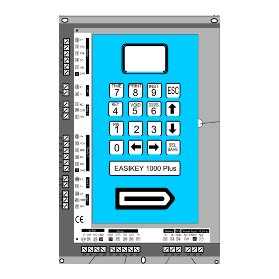
System Administration 9. System Administration 9.1 The Controller Keypad and Display This section describes how to use the controller keypad to administer the system. Figure 16 Controller Keypad and Display 9.2 Editor Keys In order to perform any administration on the system, an editor key is required. This allows the operator to access editing functions at the controller and also to accept alarms. -
Page 34: How To Use An Editor Key
System Administration 9.3 How to use an Editor Key Whenever any changes need to be made to the system an editor key should be presented to the built-in key reader. If the key is valid the screen will display From this point, press SEL? one of the following keys: PIN/1... -
Page 35: Power Indicators
Displays and Alarms 10. Displays and Alarms The Easikey 1000 door controller will display various characters on its 4-character screen and produce a sound as a response to certain conditions. These are described below. Also included in this section are example printer reports produced when a printer is attached to an Easikey 1000. -
Page 36: Unauthorised Access Alarm
Displays and Alarms 10.4 Unauthorised Access Alarm This alarm will only be given if door monitoring is being used - check with the installer of the system to see if this is the case. If a door is opened without a key being used, time profile being active, manual unlock used or a Request to Exit switch being pressed, the controller interprets this condition as Unauthorised Access. -
Page 37: Cable Or Reader Tamper Alarm
Alarm Cleared 10.7 Alarm Relays In the case of the Easikey 1000 alarms (Door Left Open, Unauthorised Access and Cable or Reader Tamper), the alarm relays can be used to operate, for example, an audible alarm such as a siren, etc. -
Page 38: Key Numbers
Adding and Voiding Keys 11. Adding and Voiding Keys 11.1 Key Numbers A key, when added into the system, is given a number between 0001 and 1000. Normally when a key is added it will be given the first available number in the list. For example, if a system contained keys 0001, 0002, 0003, 0004 and 0006, the next key added would be given number 0005, the following keys would be 0007, 0008 and so on. -
Page 39: Adding A New Key
Adding and Voiding Keys 11.2.3 Adding a New Key Follow the procedure shown below for adding a new key. If you are adding more than one new key, see Section 11.3. Step Example Display Action Present an editor key to the controller reader. Press the KEY/4 key. -
Page 40: Adding Several Keys
Adding and Voiding Keys 11.3 Adding Several Keys When you want to add several keys in one go, this can be easily done by following the Section 11.2.3 procedure until the end of step 8. At this point, instead of pressing ESC take the following steps: Step Example Display... -
Page 41: Voiding A Key
Adding and Voiding Keys 11.5 Voiding a Key A key can be removed from the database provided you have the key or you know its number. Note If a key has been lost or stolen and you have a printer fitted, it may be better to edit the key’s access level to provide no access (see Section 11.2.1) rather than void it. -
Page 42: How They Work
Time Profiles 12. Time Profiles Time profiles are a powerful tool for restricting access of personnel or for automating the opening and closing of doors. Typical examples are: A public access door through which anybody can pass between 9:00am and 5:00pm, Monday to Friday, but outside these hours a key is required. -
Page 43: How To Set Time Profiles
Time Profiles 12.2 How to Set Time Profiles Setting up time profiles is achieved by presenting an editor key and pressing the TIME/7 key. The first display you will see is the status of time profile 1 shown as alternating with T1St It is best to think of the time profile database as a grid, 8 rows representing time profiles, 10 columns being one for the Status and three for each time period. - Page 44 Time Profiles Example Add time profile 5 with two time periods, 8:00am to 1:00pm Monday to Friday and 2:00pm to 6:00pm Monday to Thursday (I.e. no access allowed at lunch times or Friday afternoon): Step Example Display Action Present an editor key to the controller reader. Press TIME/7 SEL? The status of time profile 1 (may be either...
- Page 45 Time Profiles This completes the setting up of a complete time profile. 17047 Ver 1.8 DRAFT C Easikey® 1000...
-
Page 46: Adding An Editor Key
Editor Keys 13. Editor Keys This section describes how to administer editor keys. These functions can only be performed when using the master key. The system allows up to 5 editor keys to be assigned, each one being able to accept alarms, and use Editor mode. -
Page 47: Setting The Clock
14.2 Display PIN Where a PIN reader is being used with the Easikey 1000, it is necessary to know the PIN before the key is issued as the key must be presented to the reader and the PIN entered to open the door. -
Page 48: To Lock/Unlock A Door
14.5 Printer Functions 14.5.1 Transaction Logging All Easikey 1000 door controllers keep a record of the most recent 1000 transactions, a transaction being any of the different types of event that may occur such as Access Authorised, Manual Lock, Automatic Lock, Editor On, etc. (see Appendix C -Transactions for details of all the different types of transaction). -
Page 49: User Selected Reports
..printing personnel database / Prnt ..printing time profiles / Prnt ..printing door data / Prnt Press ESC to leave Editor mode. SEL? Sample Database Printout Easikey 1000 SYSTEM PERSONNEL PRINTOUT 05/06/93 11:10 page 01 ID KEYCODE DOORS TIME 1 TIME 2... -
Page 50: Printing Selected Key Transactions
There may be a short pause while the controller searches through all the transactions. Printing transactions /Prnt Press ESC to leave Editor mode. SEL? Sample Transaction Printout for User 45 Easikey 1000 SYSTEM PERSONNEL PRINTOUT 05/06/93 11:10 page 01 DATE... - Page 51 Boxed Easikey 1000 with 1.5A PSU (in metal case) 21448 Boxed Easikey 1000 with 3.0A PSU (in metal case) 21453 Boxed Easikey 1000 with 1.5A ac PSU (in metal case with cutout) 21452 Boxed Easikey 1000 with 3.0A ac PSU (in metal case with cutout) Easi Readers...
-
Page 52: Introduction
16. Appendix B - Using External Readers 16.1 Introduction Two different types of ID device can be used on each Easikey 1000, one of which must be a proximity key (card). System administration is via the built-in reader for proximity keys/cards and via an external reader attached to the controller for other types of ID devices. -
Page 53: Avr Readers
Appendix B - Using External Readers 16.4 AVR Readers Where an AVR reader is connected to the Easikey 1000, administration is exactly the same as for key administration. For example, to add an AVR to the system the procedure is as described in Section 11.2.3. - Page 54 Appendix C -Transactions 17. Appendix C -Transactions Normal Entry and Exit Normal key authorisation. Access Authorised Only used when anti-pass back or interlock is set. Key Entry Authorised has entered area. Only used when anti-pass back or interlock is set. Key Exit Authorised has left the area.
- Page 55 Appendix C -Transactions Other Events An editor key has entered Editor mode. Editor On An editor key has left the Editor mode or the Editor Editor Off mode has timed-out. Special use of Request to Exit switch. The switch is Emergency Override On monitoring an Emergency switch (e.g.
- Page 56 Appendix C -Transactions This page is intentionall left blank. 17047 Ver 1.8 DRAFT C Easikey® 1000...
- Page 57 Appendix C -Transactions This page is intentionally left blank. 17047 Ver 1.8 DRAFT C Easikey® 1000...
- Page 58 Manufacturer's Address 1 Park Gate Close, Bredbury, Stockport, U.K. SK6 2SZ Type of Equipment Access Control Systems Product Equipment Easikey 1000 Series I, the undersigned, hereby declare that the equipment specified above conforms to the above directive(s) and standard(s). Signed Date...
Need help?
Do you have a question about the Easikey 1000 and is the answer not in the manual?
Questions and answers
What fob other than the Stanley can be used with this system?
The International Easikey 1000 system can use the PAC electronic proximity key (token) with part number 21020, besides the Stanley fob.
This answer is automatically generated