Advertisement
Quick Links
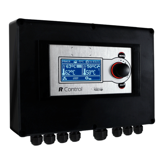
Boiler Controller
RControl EM890
producer:
FOR BOILERS FUELLED WITH PELLETS
* functions available in additional module B
** functions available in additional module MX.03
*** room panel ecoSTER200 (non standard option)
USER MANUAL FOR MAINTENANCE AND INSTALLATION
EDITION: 1.0
APPLIES FOR
HARDWARE:
MODULE A
MODULE B
v01.XX.XX
v.01.XX.XX
2012-09-10
PANEL
v.01.XX.XX
Advertisement

Summary of Contents for BurnPell RControl EM890
- Page 1 Boiler Controller RControl EM890 producer: FOR BOILERS FUELLED WITH PELLETS * functions available in additional module B ** functions available in additional module MX.03 *** room panel ecoSTER200 (non standard option) USER MANUAL FOR MAINTENANCE AND INSTALLATION EDITION: 1.0 APPLIES FOR...
- Page 3 INDEX SAFETY P RECAUTIONS ........ 5 STORAGE A ND T RANSPORT C ONDITIONS .. 22 GENERAL I NFORMATION ........ 6 ...
- Page 4 17.4 NETWORK F USE R EPLACEMENT .... 4 0 17.5 CONTROL P ANEL R EPLACEMENT .... 4 0 LAMBDA P ROBE Λ .......... 4 1 ...
- Page 5 The controller must be installed by the ⇒ 1. Safety precautions boiler producer, in accordance with valid norms and regulations. Safety requirements are described in following sections this user’s Modification programmed ⇒ manual. Apart from them please obey parameters should only be carried by requirements described below.
- Page 6 4. Documentation storage 2. General information We advise you to keep carefully this The controller is a modern electronic device user manual of installation and designed to handling the work of the pellet maintenance and all other valid boiler using help of optical flame brightness documentation, for immediate use when sensor.
- Page 7 USER MANUAL FOR CONTROLLER R.Control 890...
- Page 8 7. User menu structure Mixer settings 1,2,3,4,5 Mixer preset temperature Main menu Room mixer thermostat Mixer weather control* Information Mixer heating curve* Boiler settings Parallel curve movement* HW settings* Room temperature factor* Mixer settings 1* Mixer settings 2* Night time reductions Mixer settings 3* Boiler Mixer settings 4*...
-
Page 9: Buttons D Escription
4. Functions having influence preset 8. Controller handling boiler temperature. Following symbols this chapter shortened controller’s signal respectively: handling is described. ,,T” Preset boiler temperature decrease 8.1. BUTTONS DESCRIPTION due to thermostat disconnection; ,,S” Preset boiler temperature decrease due to activated time spans; ,,C”... - Page 10 3, 4, 5), info or HW by twisting the “TOUCH 8.5. FIRING UP and PLAY” knob. FIRING UP mode is for automatic firing up of burner in boiler. Total time of firing up Right window on the main screen may also process is depending on controller’s settings display the fuel level view, providing that this (feeder operation time, igniter operation...
- Page 11 influence on actual boiler’s power level. Power levels parameters are available in the menu: Menu → Boiler settings → Power modulation. The controller regulates burner’s power with Pic. 6 . Fan and feeder operation periods. which operates depending preset temperature defined hysteresis Parameters related to Operation mode are:...
- Page 12 Attention: boiler operates Maximum time boiler’s operating without heat buffer and controller is supervision mode is defined in parameter switched into SUMMER mode than Supervision time. If after this time (in Standard mode operation Supervision mode) there is no need to controller is recommended.
- Page 13 Set simultaneous operation of CH and • It is absolutely important to inform HW pump with the parameter all the inmates about activating the priority, disinfection function. There is a Activate function Summer. • danger of scalding with HW hot water.
- Page 14 Using parameter Parallel curve movement automatically, constantly correct heating set required room temperature according to cycle temperature. formula: Required room temperature 20°C It is not recommended to use both these heating curve parallel movement. possibilities at the same time. Example. To reach room temperature 25°C value of Automatic correction of room temperature is heating curve movement must be set for...
- Page 15 For mixer cycle: Mixer settings 1 → Mixer Preset temperature, counted according to room thermostat = 0 heating curve can be decreased or increased case connected room panel by controller when it goes beyond scope of ecoSTER200 additionally room limits of temperatures for given cycle. temperature factor 8.17.
- Page 16 Settings of time control of circular pump are Attention, defining time periods analogical to settings of night reductions. In during one day must be started at defined time periods circular pump 00:00! deactivated. In omitted periods the circular pump switched into position Circular...
- Page 17 refilled anytime, that means it is not needed to wait till the silo is empty. However fuel After connecting extension module should be filled up to the level corresponding mixers information about to 100% and set the controller level by auxiliary mixers are displayed pressing knob.
- Page 18 USER MANUAL FOR INSTALLING THE CONTROLLER SERVICE SETTINGS R.Control 890...
- Page 19 9. Hydraulic schemes 9.1. SCHEME 1 Scheme with 4 way steering valve controlling central heating circuit , where: 1 – boiler, 2 – burner, 3 Pic. 17 – controller, 4 – boiler temperature sensor, CT4, 5 – fumes temperature sensor, 6 – servomotor of 4 way valve, 7 –...
- Page 20 9.2. SCHEME 2 Scheme with heating buffer , where: 1 – boiler, 2 – burner, 3 – controller, 4 – boiler temperature Pic. 18 sensor, 5 – fumes temperature sensor, 6 – boiler pump, 7 – heating buffer, 8 – hot water pump, 9 – hot water silo, 10 –...
- Page 21 9.3. SCHEME 3 Scheme with heating buffer and 5 mixing heating circuits , where: 1 – boiler, 2 – burner, 3 – Pic. 19 controller, 4 – boiler temperature sensor CT4, 5 – fumes temperature sensor CT2S, 6 – boiler pump, 7 – heating buffer, 8 –...
-
Page 22: Environmental C Onditions
11. Storage and transport conditions 10. Technical data controller exposed Power 230V~; 50Hz; immediate effects of atmospheric conditions i.e. rain or sunrays. Temperature of storage Current consumed by controller I = 0,04 A and transport should be within scope -15…65 Maximum nominal current 6 (6) A degrees C. -
Page 23: Installation
12.3. INSTALLATION The controller is adapted to be installed on flat assembly surface. In order to screw it to assemble surface please undo the screws (3) and carefully lift the cover (1), then undo the plug (4). Then remove the cover (1) in a safe place. Using screws (5) stuck through holes in the cover (2) screw the controller to assembly surface (6). - Page 24 Connecting wires should not touch with surfaces with temperatures exceeding nominal temperature of their work. Claps on the right side of the device are marked as L, N, 1-19 are designed to connect devises powered with current 230V~. Claps 20-40, D+, D- and RJ are designed to cooperate with low voltage devices (below 12V).. Connecting current 230V to claps 20 –...
-
Page 25: Safety C Onnections
12.5. SAFETY CONNECTIONS Safety wires are to be connected with terminals marked with this symbol 12.6. ELECTRIC SCHEME Pic. 22 Scheme of electrical connections of the controller, where: T1 – boiler temperature sensor CT4, T2 – hot water temperature sensor CT4, T3 – feeder temperature sensor, OS – flame optical sensor, AL/RB – currency exit to alarm signal or steering the auxiliary silo, RELAY –... - Page 26 To connect use wire with diameter at least 12.7. TEMPERATURE SENSORS CONNECTION 0,5 mm up to 25 m long. Polarization of wires is not essential. Second end should be connected terminals controller Wires of the sensors can be extended by according to Pic.
-
Page 27: Mixer C Onnection
CT2S-2 fumes Temp. Min. Nom. Max. 12.12. BOILER ROOM THERMOSTAT °C Ω Ω Ω CONNECTION 999,7 1000,0 1000,3 1096,9 1097,3 1097,7 Room thermostat for boiler circuit can switch 1193,4 1194,0 1194,6 off the burner operation or switch off the CH 1384,2 1385,0 1385,8... - Page 28 Assembly of transmitter should Switching controller into be done by a person with proper STAND-BY mode causes qualifications, according to valid deactivating the additional boiler. norms and regulations. To activate control over additional boiler set parameter Additional boiler deactivation temperature value different than zero.
- Page 29 Pic. 27 External alarm device connection, where: 1 – controller, 2- external alarm device, 3- transmitter Then in order to operate correctly set proper code for active alarms signal in menu: Menu Service settings Boiler → → settings → Alarms Choosing value „127”...
- Page 30 any of alarms is to be reported AL2, AL3 – Connect electrical power to mixer set parameter for “6” servomotor with controller, according to point 12.4 and value servomotor producer’s 12.15. MIXER CONNECTION documentation. confuse opening direction with closing During assembly works for mixer direction, servomotor pay attention not to Connect...
-
Page 31: Temperature L Imiter C Onnection
Room thermostat (controls up to 3 thermostats) 12.17. TEMPERATURE LIMITER CONNECTION Controlling panel for the boiler In order not to overheat the boiler due to the Alarm signal controller breakdown it is obligatory to use Fuel level indicator STB safety temperature limiter or any other 4 way connection: one suitable for given boiler. - Page 32 • Cycle time 13. Structure – service menu • Blowing power Min. blowing power Service settings Lack of fuel detection time Burner settings Feeder max. temperature Boiler settings Additional feeder operation time HW and CH settings Buffer settings* Boiler settings Mixer settings 1* Thermostat selection Mixer settings 2*...
-
Page 33: Other
14. Service settings 14.1. BURNER SERVICE SETTINGS Burner settings Description Firing up Time for checking if furnace is hot. Only fan is operating • Ignition test time Time for feeding fuel when firing up. It refers to the first attempt. In next •... - Page 34 Cleaning Fan operation time during cleaning the furnace while firing up • Firing up cleaning time Fan operation time during furnace burning off • Burning off cleaning time Fan power in % during furnace cleaning in burning off and firing up •...
- Page 35 increase return temperature. Minimum preset boiler temperature which can be set in user menu and Boiler minimum temperature minimum temp. which can be set automatically by controller, i.e. from night reductions etc. Maximum preset boiler temperature which can be set in user menu and Boiler maximum temperature minimum temp.
- Page 36 Available after connecting HW sensor. After feeding HW silo and deactivating HW pump may be a risk of boiler overheating. It happens in case when preset HW temperature was higher than boiler preset Prolongation of HW operation* temperature. This issue is exceptionally important in HW pump operation in SUMMER mode, when pump is deactivated.
- Page 37 Universal – standard thermostat connected to terminals 28-30 for • mixer 1, for mixers 2,3,4,5 use proper terminals in additional modules. ecoSTERT1 – thermostat 1 in ecoSTER200, • ecoSTERT2 – thermostat 1 in ecoSTER200, • ecoSTERT3 – thermostat 1 in ecoSTER200, •...
- Page 38 14.6. ADVANCE PARAMETERS Options available: YES (displays hidden parameters which edition is not • Show advanced recommended) NO (hides hidden parameters) • 15. Default settings restoring Default settings restore Restoring service settings. Settings from main menu are restored.
- Page 39 16. Alarm descriptions 16.1. BOILER MAX. TEMPERATURE Alarm is deleted automatically after feeder EXCEEDING temperature decrease by 10°C. Protection against boiler overheating is done in 2 steps. In the first step, after exceeding Function which protects against Boiler cooling off temperature, the controller back fire...
- Page 40 It is necessary to check the sensor and replace it if necessary. 16.7 Failed attempt of feeding the silo This is so called silent alarm reminder. It will Checking temperature sensor take place by failed attempt of feeding fuel described in point 12.9. from additional silo.
- Page 41 should be used. In order to take out the fuse time of air amount in fumes to preset unscrew the fuse cover and remove the fuse. amount and on stability of air in fumes. It is recommended change these 17.5. CONTROL PANEL REPLACEMENT parameters if regulation time and stability of keeping preset amount of air on required It is not recommended to replace the panel...
-
Page 42: C Onnection
19. Description of possible faults Symptoms Tips 1. There are no signs of Check: operation device § If line fuses are not blown, replace if necessary. despite connection § If the wire connecting panel with the executive module is plugged the network. - Page 43 § The cause may be HW silo loading when HW priority is activated. Wait until HW is loaded or activate the HW priority. § The cause may be active function SUMMER. § The cause may be activation of function return protection (Menu → Service settings →...
Need help?
Do you have a question about the RControl EM890 and is the answer not in the manual?
Questions and answers