Table of Contents
Advertisement
Title Page
Prev Page
2A-23-10: General
The Gulfstream G550 communications system provides the flight crew audio links within
the aircraft, and radio links to other aircraft and ground stations. Transmitter and audio
reception selections are made using pushbuttons on the audio panels installed at the
pilot, copilot and observer stations. (See Figure 1.)
The communications system is divided into the following subsystems:
• 2A-23-20: Audio Panels
• 2A-23-30: Voice Communication Systems
• 2A-23-40: MCDU and CCD Radio Tuning
• 2A-23-50: Selective Calling System
• 2A-23-60: Cockpit Voice Recorder System
• 2A-23-70: Emergency Locator Transmitter
PRODUCTION AIRCRAFT SYSTEMS
Next Page
TOC
OPERATING MANUAL
COMMUNICATIONS
2A-23-00
Page 1
December 5/03
Advertisement
Table of Contents

Related Manuals for Gulfstream G550


Summary of Contents for Gulfstream G550
- Page 1 COMMUNICATIONS 2A-23-10: General The Gulfstream G550 communications system provides the flight crew audio links within the aircraft, and radio links to other aircraft and ground stations. Transmitter and audio reception selections are made using pushbuttons on the audio panels installed at the pilot, copilot and observer stations.
- Page 2 Title Page Prev Page Next Page OPERATING MANUAL THIS PAGE IS INTENTIONALLY LEFT BLANK. 2A-23-00 PRODUCTION AIRCRAFT SYSTEMS Page 2 December 5/03...
- Page 3 Title Page Prev Page Next Page OPERATING MANUAL Communications System Components Figure 1 2A-23-00 Page 3 / 4 December 5/03...
- Page 4 Title Page Prev Page Next Page...
- Page 5 Title Page Prev Page Next Page OPERATING MANUAL 2A-23-20: Audio Panels 1. General Description: Three AV-900 audio panels are installed in the cockpit: one at each pilot seat and one at the observer station. All panels are identical, and a typical panel is shown in Figure 2.
- Page 6 Title Page Prev Page Next Page OPERATING MANUAL A. Transmit Button Selections: The ten rectangular transmit buttons on the audio panel illuminate green when selected. Selection of a transmit button will automatically select the corresponding audio reception. (1) COM 1, COM 2 and COM 3 selections transmit voice or data over the selected VDR / VHF radio, tuned with the MCDU.
- Page 7 Title Page Prev Page Next Page OPERATING MANUAL The hand held microphones may be used at any time regardless of the MIC pushbutton selection. The EMER “backup” pushbutton on ACP 1 (pilot) and ACP 2 (copilot) controls a relay within the respective ACP that selects normal digitized audio panel operation when pushed in, or selects a direct analog wire connection from headsets and microphones to VHF COM #1 when pulled out.
- Page 8 Title Page Prev Page Next Page OPERATING MANUAL E. Audio Panel Volume Control: The large round knob on the audio panel labeled SET controls the overall volume setting of the selected audio inputs to the panel. A numerical value associated with the set volume level is displayed in the LED indicator to the left of the knob when the knob is used.
- Page 9 Title Page Prev Page Next Page OPERATING MANUAL A. Circuit Breakers (CBs): The audio panels are protected by the following CBs: Circuit Breaker Name: CB Panel: Location: Power Source: PILOT ACP LEER D-17 L EMER 28v DC Bus COPILOT ACP REER R ESS 28v DC Bus OBSERVER ACP...
- Page 10 Title Page Prev Page Next Page OPERATING MANUAL THIS PAGE IS INTENTIONALLY LEFT BLANK. 2A-23-00 PRODUCTION AIRCRAFT SYSTEMS Page 10 December 5/03...
- Page 11 Title Page Prev Page Next Page OPERATING MANUAL Audio Control Panel Figure 2 2A-23-00 Page 11 / 12 December 5/03...
- Page 12 Title Page Prev Page Next Page...
- Page 13 Title Page Prev Page Next Page OPERATING MANUAL 2A-23-30: Voice Communication Systems 1. General Description: The voice communication system provides a means for the crew to exchange information and data with other aircraft and ground-based stations. It is composed of the following subsystems: •...
- Page 14 Title Page Prev Page Next Page OPERATING MANUAL antenna, B. High Frequency (HF) Communication System: The HF communication system provides long range voice and data communication capabilities to and from the aircraft. HF # 1 and HF # 2 are independent receiver / transmitters (R/Ts) utilizing a dual coupler mount to interface with a common antenna.
- Page 15 Title Page Prev Page Next Page OPERATING MANUAL telephone handsets, PC modems or FAX machines) and any operating telephone or data unit within the coverage of the International Maritime Satellite Organization (INMARSAT). Coverage is provided by four (4) or more geo-stationary satellites operating in the L band of the radio spectrum, providing global communications linkage except in the polar regions (north or south of seventy-five degrees latitude).
- Page 16 Title Page Prev Page Next Page OPERATING MANUAL (5) Audio Control Panel (ACP) SAT transmit button - enables the flight crew to communicate over the SATCOM system using headsets and boom or conventional microphones. Each of the three (3) ACPs is connected via the Network Interface Module (NIM) in Modular Radio Cabinet (MRC) #2 to the SDU that converts analog voice into a digital signal for transmission to the relaying satellite.
- Page 17 Title Page Prev Page Next Page OPERATING MANUAL adjacent to the ANSWER CALL command • Communicate with either the boom or handheld microphone To place current SATCOM call on hold: • If other communications require a higher priority while making a SATCOM call, selecting any of the communication radio mic buttons (COM1, COM2, COM3, HF1, HF2) will automatically place the active SATCOM call on hold and the SAT mic button will flash at 3...
- Page 18 Title Page Prev Page Next Page OPERATING MANUAL (2) Cockpit Audio Control Panel (ACP) interface - allows the flight crew to place and answer calls using headphones and boom or hand microphones without using the cockpit digital handset. The telephone symbol adjacent to the SAT, CABIN, CONF and FONE transmit buttons indicates that these functions are available through the MagnaStarT system.
- Page 19 Title Page Prev Page Next Page OPERATING MANUAL B. Crew Alerting System (CAS) Messages: CAS messages associated with the voice communication systems are: Area Monitored: CAS Message: Message Color: MRCs MRC 1-2 Overheat Amber MRCs MRC 1-2 Fail Amber VHF COM 1-2 VDRs Amber Overheat...
- Page 20 Title Page Prev Page Next Page OPERATING MANUAL Modular Radio Cabinet Figure 3 2A-23-00 PRODUCTION AIRCRAFT SYSTEMS Page 20 December 5/03...
- Page 21 Title Page Prev Page Next Page OPERATING MANUAL SATCOM Antenna Figure 4 2A-23-00 PRODUCTION AIRCRAFT SYSTEMS Page 21 December 5/03...
- Page 22 Title Page Prev Page Next Page OPERATING MANUAL SATCOM and MagnaStarT MASTER Switches Figure 5 2A-23-00 PRODUCTION AIRCRAFT SYSTEMS Page 22 December 5/03...
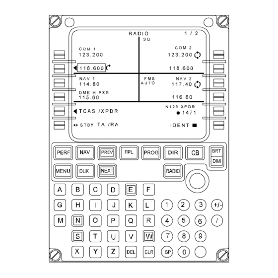
- Page 23 Title Page Prev Page Next Page OPERATING MANUAL 2A-23-40: MCDU and CCD Radio Tuning 1. General Description: Communication and navigation radios are tuned using functions contained in the Multi-function Control and Display Unit (MCDU) RADIO pages or by commands using the Cursor Control Device (CCD) and frequency data on the Display Units (DUs).
- Page 24 Title Page Prev Page Next Page OPERATING MANUAL 3. Controls and Indications: A. Circuit Breakers (CBs): The radio tuning system is protected by the following CBs: Circuit Breaker Name: CB Panel: Location: Power Source: MCDU #1 R EMER DC Bus MCDU #2 CPOP R MAIN DC Bus...
- Page 25 Title Page Prev Page Next Page OPERATING MANUAL MCDU Radio Tuning Figure 6 2A-23-00 PRODUCTION AIRCRAFT SYSTEMS Page 25 December 5/03...
- Page 26 Title Page Prev Page Next Page OPERATING MANUAL 2A-23-50: Selective Calling System 1. General Description: The selective calling (SELCAL) system provides a means for ground stations to address specific aircraft over normal communication frequencies without requiring the flight crew to continually monitor the frequencies for incoming transmissions. The SELCAL system incorporates a coded data address module for each individual aircraft.
- Page 27 Title Page Prev Page Next Page OPERATING MANUAL • CVR unit • Voice Recorder Control Unit (VRCU) • Cockpit area microphone • Bulk erase switch • Impact switch 2. Description of Subsystems, Units and Components: A. CVR Unit: The CVR is mounted in the tail compartment. A solid-state unit, it continuously records four channels of analog audio information: pilot audio panel, copilot audio panel, observer audio panel and cockpit area audio.
- Page 28 Title Page Prev Page Next Page OPERATING MANUAL maximize the reception and recording of human conversation and other ambient sound in the cockpit area. D. Bulk Erase Switch: The bulk erase switch is located on the Test and Monitor Panel at the Right Electronic Equipment Rack (REER).
- Page 29 Title Page Prev Page Next Page OPERATING MANUAL Voice Recorder Control Unit Figure 7 2A-23-00 PRODUCTION AIRCRAFT SYSTEMS Page 29 December 5/03...
- Page 30 Title Page Prev Page Next Page OPERATING MANUAL Voice Recorder Bulk Erase Switch Figure 8 2A-23-00 PRODUCTION AIRCRAFT SYSTEMS Page 30 December 5/03...
- Page 31 Title Page Prev Page Next Page OPERATING MANUAL Voice Recorder Impact Switch Figure 9 2A-23-70: Emergency Locator Transmitter 1. General: A. Description: A battery powered Emergency Locator Transmitter (ELT) unit is installed in the upper shelf of the Aft Electronic Equipment Rack (AEER) in the baggage compartment.
- Page 32 Title Page Prev Page Next Page OPERATING MANUAL • 406.025 MHz - emergency satellite locating frequency The transmission over the emergency satellite frequency (406.025) consists of a digital data block that includes the aircraft tail number, country of registration and position coordinates. (The aircraft specific digital data is strapped into the ELT unit upon initial installation.) Position data is continually furnished to the ELT over an ARINC-429 link with Inertial Reference Unit (IRU) #1.
- Page 33 Title Page Prev Page Next Page OPERATING MANUAL (1) Any ELT test should only be performed within the first five (5) minutes of the hour. Obtain a valid Universal Coordinated Time (UTC) reading prior to testing. (2) Notify any control tower or ATC facility within reception range of the intention to test the ELT and the time of the test.
- Page 34 Title Page Prev Page Next Page OPERATING MANUAL Cockpit ELT Switch Panel Figure 10 2A-23-00 PRODUCTION AIRCRAFT SYSTEMS Page 34 December 5/03...
- Page 35 Title Page Prev Page Next Page OPERATING MANUAL Baggage Compartment ELT Switch Panel Figure 11 2A-23-00 PRODUCTION AIRCRAFT SYSTEMS Page 35 December 5/03...
- Page 36 Title Page Prev Page Next Page OPERATING MANUAL THIS PAGE IS INTENTIONALLY LEFT BLANK. 2A-23-00 PRODUCTION AIRCRAFT SYSTEMS Page 36 December 5/03...
Need help?
Do you have a question about the G550 and is the answer not in the manual?
Questions and answers