
Subscribe to Our Youtube Channel
Related Manuals for CARLO GAVAZZI WM20


Summary of Contents for CARLO GAVAZZI WM20
- Page 1 WM20 INSTRUCTION MANUAL MANUALE D’ISTRUZIONI BETRIEBSANLEITUNG MANUEL D’INSTRUCTIONS MANUAL DE INSTRUCCIONES BRUGERVEJLEDNING...
-
Page 3: Table Of Contents
Breakdown of code key of main unit (rear of unit) ........ 9 Breakdown of code key of compatible accessory modules (rear of module) ..................9 Breakdown of code key of pre-assembled WM20 (rear of main unit) ... 10 ................ 10 Description of main unit 11 Main unit - front .................. - Page 4 Running a pulse transmission test ............36 Resetting maximum and average power values ........37 Resetting total energy meters ............... 38 Identifying the variable in alarm status ..........39 Troubleshooting ..................39 8021572 | WM20 | © 2016 | CARLO GAVAZZI Controls SpA...
- Page 5 General features ................... 53 ................. 54 Measurement accuracy ................ 55 Power supply ..................56 LED ....................... 57 General features ................... 58 Static output module (M O O2) ............. 58 8021572 | WM20 | © 2016 | CARLO GAVAZZI Controls SpA...
- Page 6 M C ETH module .................. 61 M C BAC IP module ................61 M C BAC MS module................62 M C PB module..................63 Conformity 64 Download 65 Figures 395 8021572 | WM20 | © 2016 | CARLO GAVAZZI Controls SpA...
-
Page 7: Introduction
It must be kept in good condition and in a clean location accessible to all operators. WARNING: no person is authorized to open the analyzer. This operation is reserved exclusively for CARLO GAVAZZI technical service personnel. 8021572 | WM20 | © 2016 | CARLO GAVAZZI Controls SpA... -
Page 8: Service And Warranty
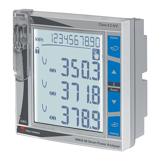
WM20 Description WM20 is a modular power analyzer for single, two and three-phase systems. It is made up of a maximum of three components: main unit that displays measurements on the LCD display with management of two alarms, and two accessory modules, one with digital outputs and the other for communication. -
Page 9: Breakdown Of Code Key Of Main Unit (Rear Of Unit)
M C ETH Modbus TCP/IP communication on Ethernet M C BAC IP Communication BACnet IP communication on Ethernet M C BAC MS BACnet MS/TP communication on RS485 M C PB 8021572 | WM20 | © 2016 | CARLO GAVAZZI Controls SpA... -
Page 10: Breakdown Of Code Key Of Pre-Assembled Wm20 (Rear Of Main Unit)
Breakdown of code key of pre-assembled WM20 (rear of main unit) WM20 AVx 3a Same as code Output type: Communication type: key of main XX: none XX: none option unit, O2: double S1: RTU Modbus communication on included see "Key to... -
Page 11: Description Of Main Unit
Detachable current input terminals Detachable voltage input terminals position 1 on display) position 7 on display) Local bus port for accessory modules Power supply status LED, see "LED" on page 57 8021572 | WM20 | © 2016 | CARLO GAVAZZI Controls SpA... -
Page 12: Main Unit - Accessories
Page title, see “Settings menu” on page 24 and “Reset menu” on page 33 Page title, see “Settings menu” on page 24 and “Reset menu” on page 33 Current value/option. Blinks when in edit mode. Possible value/option range 8021572 | WM20 | © 2016 | CARLO GAVAZZI Controls SpA... -
Page 13: Information Menu Display
Warning of at least one active alarm: permanent: on the information menu page related to the active alarm and activated digital output where relevant blinking: on the measurement menu pages 8021572 | WM20 | © 2016 | CARLO GAVAZZI Controls SpA... -
Page 14: Description Of Accessory Modules
NOTE: the communication ports depend on the communication Main unit fastening pins Communication status LED (M C 485232, M C BAC MS, M C PB), see "Communication module overview" on page 42. 8021572 | WM20 | © 2016 | CARLO GAVAZZI Controls SpA... -
Page 15: Installation
See “Main unit connection diagrams” on page 18 and “Accessory module connection diagrams” on page 19. To seal the See “Sealing the main unit terminals” on page 11 terminal caps on the main unit 8021572 | WM20 | © 2016 | CARLO GAVAZZI Controls SpA... - Page 16 1. Connect to the WM20 via a Modbus RTU or Modbus TCP/IP communication port or via software optical port using OptoProg. 2. Modify the parameters from the settings menu 8021572 | WM20 | © 2016 | CARLO GAVAZZI Controls SpA...
-
Page 17: Sealing The Terminals On The Main Unit
2. Apply the four seals, each in a hole of the main unit [A]. 4. Position the terminal caps, passing the seals through the corresponding holes of the caps [B]. 5. Close the seal. 8021572 | WM20 | © 2016 | CARLO GAVAZZI Controls SpA... -
Page 18: Installing The Accessory Modules
Fig.15 Three-phase system with neutral (4-wire), balanced load, 1 CT 3P.2 and 1 VT/PT Fig.16 Three-phase system without neutral (3-wire) unbalanced load and 3 CT. 315 mA fuse (F). 8021572 | WM20 | © 2016 | CARLO GAVAZZI Controls SpA... -
Page 19: Accessory Module Connection Diagrams
Auxiliary power supply (L). 250 V [T] 3.15 A fuse (F) Accessory module connection diagrams Diagram Description Fig.27 M O O2. Double static opto-mosfet output. M O R2. Double relay output. 8021572 | WM20 | © 2016 | CARLO GAVAZZI Controls SpA... -
Page 20: Use: Menu Description
-- Total exported active energy kvarh -- Total exported reactive energy h Load operating hours with current absorption exceeding the set threshold, see “Settings menu” on page 24 NOTE: 8021572 | WM20 | © 2016 | CARLO GAVAZZI Controls SpA... -
Page 21: List Of Measurement Pages
VA 1 Phase 1 apparent power VA 2 Phase 2 apparent power VA 3 Phase 3 apparent power NOTE: the button can be used to display the average and then maximum values. 8021572 | WM20 | © 2016 | CARLO GAVAZZI Controls SpA... - Page 22 PF System power factor A N Neutral current thd% * A 1 THD of phase 1 current A 2 THD of phase 2 current A 3 THD of phase 3 current 8021572 | WM20 | © 2016 | CARLO GAVAZZI Controls SpA...
- Page 23 V 1 Phase 1 voltage V 2 Phase 2 voltage V 3 Phase 3 voltage V 12 Phase 1-phase2 voltage V 23 Phase 2-phase3 voltage V 31 Phase 3-phase1 voltage NOTE harmonic. 8021572 | WM20 | © 2016 | CARLO GAVAZZI Controls SpA...
-
Page 24: Settings Menu
M O O2 Auto: indicates that the Modules module is automatically MCETH Module enable recognized by the system, MCBAC IP see “Enabling accessory MCBAC MS modules” on page 48 MCPB 8021572 | WM20 | © 2016 | CARLO GAVAZZI Controls SpA... - Page 25 5 s Home page to measurement menu From 1 to 14 and after 120 seconds To check the page codes, of disuse see “List of measurement pages” on page 21 8021572 | WM20 | © 2016 | CARLO GAVAZZI Controls SpA...
- Page 26 Baudrate Baud rate (kbps) 115.2 Optical Parity Parity None/ Odd/ Even Address Modbus address From 1 to 247 Baudrate Baud rate (kbps) 9.6/ Parity Parity None/ Odd/ Even 8021572 | WM20 | © 2016 | CARLO GAVAZZI Controls SpA...
- Page 27 From 0 to 127 (1) From 0 to 9999 (via keypad) From 0 to 4194302 (via Device id Instance number communication) BACnet (9999) (continues) FD Enable Foreign Device enable Yes/ No 8021572 | WM20 | © 2016 | CARLO GAVAZZI Controls SpA...
- Page 28 Alarm activation Set 2 controlled variable. threshold Alarm activation delay Virt al 1 *** On delay From 0 to 3600 8021572 | WM20 | © 2016 | CARLO GAVAZZI Controls SpA...
- Page 29 Pulse weig kvarh per pulse) Enable of test re- Yes/No Out test transmission Dig out 1 **** Power value for test From 0.001 W to 9999 MW Power test 8021572 | WM20 | © 2016 | CARLO GAVAZZI Controls SpA...
- Page 30 Energy pos imported active and reactive energy Resets values of Energy neg exported active and reactive energy Return to measurement – menu NOTE NOTE NOTE NOTE digital output modules” on 8021572 | WM20 | © 2016 | CARLO GAVAZZI Controls SpA...
-
Page 31: Default Values Of Alarm Parameters
Voltage transformer ratio (Vt) Interval for average power calculation (min) Led pulse Weight of pulse of front LED (kWh/kvarh per pulse) Run hour Current threshold for calculating load operating hours (A) 8021572 | WM20 | © 2016 | CARLO GAVAZZI Controls SpA... - Page 32 (out1= output 1, out2 = Remote output 2) output status (ON = closed, OFF = open) 8021572 | WM20 | © 2016 | CARLO GAVAZZI Controls SpA...
-
Page 33: Reset Menu
IP address IP add 2/2 Reset menu The reset menu is made up of two pages used to reset the maximum and average power values respectively (active, apparent and reactive). 8021572 | WM20 | © 2016 | CARLO GAVAZZI Controls SpA... -
Page 34: Use: How To Work
On access to the measurement menu or after 120 seconds of disuse, the measurement page is then displayed as set in the Home Page. Common operations Operation Button View the previous/next page 8021572 | WM20 | © 2016 | CARLO GAVAZZI Controls SpA... - Page 35 Settings menu Operation Button Enter the sub-menu/Modify parameter of the page on display Increase a parameter value / View the next value option/ dP and Sign* 8021572 | WM20 | © 2016 | CARLO GAVAZZI Controls SpA...
-
Page 36: Setting A Parameter
Running a pulse transmission test transmission can be run. 1. In the settings menu, enter the sub-menu Dig out 1 or Dig out 2 (depending on the digital output concerned) Function = Puls) 8021572 | WM20 | © 2016 | CARLO GAVAZZI Controls SpA... -
Page 37: Resetting Maximum And Average Power Values
6. View the next page (Reset dmd). 7. Modify the parameter and select the option YES. active, apparent and reactive energy are reset. 8021572 | WM20 | © 2016 | CARLO GAVAZZI Controls SpA... -
Page 38: Resetting Total Energy Meters
7. View the next page (Energy neg). 8. Modify the parameter and select the option YES. exported active and reactive energy are reset. 8021572 | WM20 | © 2016 | CARLO GAVAZZI Controls SpA... -
Page 39: Identifying The Variable In Alarm Status
Al 1/Al 2 and/or Alarm and if the relative alarm is active, the symbol remains permanently lit. For a description of the alarms see “Information menu” on page 31. NOTE: Troubleshooting NOTE: distributor in your country. 8021572 | WM20 | © 2016 | CARLO GAVAZZI Controls SpA... - Page 40 The value entered is out of range Check the range of while the admissible values on the parameter is relative page displayed or being set see “Settings menu” on page 24 and re-enter the value. 8021572 | WM20 | © 2016 | CARLO GAVAZZI Controls SpA...
- Page 41 The alarm is The alarm settings are incorrect Check the parameters set not activated or in the settings menu, see deactivated as “Settings menu” on page expected 8021572 | WM20 | © 2016 | CARLO GAVAZZI Controls SpA...
- Page 42 7 It is impossible to change the The user is in the settings menu Exit the settings menu settings (via pressing UCS software) for 1.5 s 8021572 | WM20 | © 2016 | CARLO GAVAZZI Controls SpA...
-
Page 43: Essential Information
In the position dP (decimal point) the buttons can be used to enable movement of the decimal point and set a multiplier (k x 1000, M x 1000000) in the following order: 8021572 | WM20 | © 2016 | CARLO GAVAZZI Controls SpA... -
Page 44: Address Parameters
HI) on page 1/2 and second part (LO) on page 2/2. For example the pages IP add 1/2 and IP add 2/2 with the address set as 192.168.2.18 will be as follows: 8021572 | WM20 | © 2016 | CARLO GAVAZZI Controls SpA... -
Page 45: Alarm Settings
If Set 1 > Set 2, the alarm is activated when the controlled variable exceeds the value of Set 1 for a time equal to On delay and is deactivated when it falls below Set 2. 8021572 | WM20 | © 2016 | CARLO GAVAZZI Controls SpA... -
Page 46: Filter Settings
Filter settings Operation to external systems). NOTE: Filter s: percentage of the full scale of the variable. Filter co: enables maximum stability of the measurements. Filter s not applied. 8021572 | WM20 | © 2016 | CARLO GAVAZZI Controls SpA... - Page 47 Element Description Intervention range with Filter s = 2 Measured value Measurements displayed with Filter co = 2 Measurements displayed with Filter co = 10 8021572 | WM20 | © 2016 | CARLO GAVAZZI Controls SpA...
-
Page 48: Enabling The Accessory Modules
The module must be enabled via the M O R2 Manual settings menu, see “Settings menu” on M O O2 page 24 NOTE *: module enabled only if no other communication module has been installed. 8021572 | WM20 | © 2016 | CARLO GAVAZZI Controls SpA... - Page 49 A pulse transmission test can Test transmission be run. enable (Out test) Power value for test (Power test) NOTE To set alarm parameters, see “Settings menu” on page 24. 8021572 | WM20 | © 2016 | CARLO GAVAZZI Controls SpA...
-
Page 50: Maintenance And Disposal
Do not use abrasives or solvents. Responsibility for disposal government or local public authorities. Correct disposal and recycling will contribute to the prevention of potentially harmful consequences to the environment and persons. 8021572 | WM20 | © 2016 | CARLO GAVAZZI Controls SpA... -
Page 51: General Features
100 dB, from 42 to 62 Hz (CMRR) double electrical insulation on areas accessible to the user. Insulation For insulation between inputs and outputs, see "Input and output insulation" on page 52. 8021572 | WM20 | © 2016 | CARLO GAVAZZI Controls SpA... -
Page 52: Input And Output Insulation
2, double insulation on system with maximum 300 Vrms grounding) Operating temperature From -25 to +55 °C/from -13 to +131 °F Storage temperature From -30 to +70 °C/from –22 to +158 °F NOTE: 8021572 | WM20 | © 2016 | CARLO GAVAZZI Controls SpA... -
Page 53: General Features
General features Mounting Panel mounting Dimensions (mm) 22,2 27,9 8021572 | WM20 | © 2016 | CARLO GAVAZZI Controls SpA... -
Page 54: Current Inputs
For 500 ms: 2 Un max Input impedance From 40 to 440 Hz Current inputs Current connection Via CT CT transformation ratio From 1 to 9999 Rated current (In) 8021572 | WM20 | © 2016 | CARLO GAVAZZI Controls SpA... -
Page 55: Measurement Accuracy
From Un min -20% to Un ±(0.5% rdg +1dgt) max + 15% Active and apparent power From 0.05 In to Imax ±(0.5% rdg +1dgt) From 0.01 In to 0.05 In ±(1% rdg +1dgt) (PF=1) 8021572 | WM20 | © 2016 | CARLO GAVAZZI Controls SpA... -
Page 56: Power Supply
From 45 to 65 Hz ±0.1 Hz Power supply From 100 to 240 V ac/dc From 24 to 48 V ac/dc Auxiliary power supply ± 10% ± 15% Consumption 3.5 W, 6 VA 8021572 | WM20 | © 2016 | CARLO GAVAZZI Controls SpA... -
Page 57: Led
From 7001 to 70 k > 70.01 k The page Led pulse in the information menu displays the weight of the pulse. Back Green. Lit when WM20 is powered. 8021572 | WM20 | © 2016 | CARLO GAVAZZI Controls SpA... -
Page 58: General Features
: 2.5 V dc, 100 mA max Features : 42 V dc max Settings menu, sub-menus Dig out 1 and Dig out 2, see “Settings menu” on page 24 Via keypad or UCS software 8021572 | WM20 | © 2016 | CARLO GAVAZZI Controls SpA... -
Page 59: Relay Output Module (M O R2)
Via keypad or UCS software Communication module overview General features Mounting On main unit (with or without digital output module) Dimensions (mm) Power supply Self power supply via local bus 89,49 8021572 | WM20 | © 2016 | CARLO GAVAZZI Controls SpA... -
Page 60: M C 485232 Module
Max 160 (1/5 unit load) Communication type Two-way Connection type 3 wires, maximum distance 15 m Settings menu, sub-menu , see “Settings menu” on page 24 Via keypad or UCS software NOTE: 8021572 | WM20 | © 2016 | CARLO GAVAZZI Controls SpA... -
Page 61: M C Eth Module
(Modbus only) Maximum 5 simultaneously RJ45 connector (10 Base-T, 100 Base-TX), maximum Connection type distance 100 m Settings menu, sub-menus Ethernet and BACnet, see “Settings menu” on page 24 8021572 | WM20 | © 2016 | CARLO GAVAZZI Controls SpA... -
Page 62: M C Bac Ms Module
Maximum 5 simultaneously RJ45 connector (10 Base-T, 100 Base-TX), maximum Connection type distance 100 m Settings menu, sub-menu Ethernet, see “Settings menu” on page 24 Via keypad or UCS software 8021572 | WM20 | © 2016 | CARLO GAVAZZI Controls SpA... -
Page 63: M C Pb Module
(see relative illustration sheet) Via keypad or UCS software Micro-USB port Protocols Modbus RTU Type USB 2.0 (USB 3.0 compatible) Connection type Micro-USB B Baud rate Any (maximum 115.2 kbps) Address 8021572 | WM20 | © 2016 | CARLO GAVAZZI Controls SpA... -
Page 64: Conformity
Electrical safety: EN61010-1 Metrology: EN62053-22, EN62053-23 Pulse outputs: IEC62053-31, DIN43864 Approvals Download The site www.productselection.net enables users to download: UCS software datasheets and manual of the WM20 in PDF format 8021572 | WM20 | © 2016 | CARLO GAVAZZI Controls SpA...
Need help?
Do you have a question about the WM20 and is the answer not in the manual?
Questions and answers