Table of Contents
Advertisement
Quick Links
VIBRATION TRANSMITTER-VT7S12E
Ref No: mVTD/om/201
Issue No: 02
USER MANUAL
VT7S12E
VIBRATION TRANSMITTER
Masibus Automation & Instrumentation Pvt. Ltd.
B/30, GIDC Electronics Estate,
Sector-25, Gandhinagar-382044, Gujarat, India
+91 79 23287275-79 +91 79 23287281-82
Email: support@masibus.com
Web: www.masibus.com
User's Manual
- 1 -
Advertisement
Table of Contents

Summary of Contents for Masibust VT7S12E
- Page 1 VIBRATION TRANSMITTER-VT7S12E Ref No: mVTD/om/201 Issue No: 02 USER MANUAL VT7S12E VIBRATION TRANSMITTER Masibus Automation & Instrumentation Pvt. Ltd. B/30, GIDC Electronics Estate, Sector-25, Gandhinagar-382044, Gujarat, India +91 79 23287275-79 +91 79 23287281-82 Email: support@masibus.com Web: www.masibus.com User’s Manual - 1 -...
-
Page 2: Table Of Contents
VIBRATION TRANSMITTER-VT7S12E Ref No: mVTD/om/201 Issue No: 02 CONTENTS CONTENTS ................................2 LIST OF TABLE ................................ 3 LIST OF FIGURE ..............................3 1. INTRODUCTION ..............................4 2. INSTALLATION ..............................5 3. HARDWARE SPECIFICATION DETAIL ........................6 3.1 Input specification ..........................6 3.2 Power supply specification ...................... -
Page 3: List Of Table
Table 41 Retransmission Output during Open/Over Condition ............. 28 LIST OF FIGURE Figure 1 Front Panel Description ........................8 Figure 2 Connection Diagram of VT7S12E ....................9 Figure 3 Level-1 Flow Diagram ........................10 Figure 4 Level-1, Level-2, Calibration & Factory Reset Mode Flow Diagram ..........11 User’s Manual... -
Page 4: Introduction
1. INTRODUCTION F o r e w o r d Thank you for purchasing VT7S12E - Vibration Transmitter. This manual describes the basic functions and operation methods of VT7S12E.Please read through this user‟s manual carefully before using the product. This is a 8 bit controller based instrument designed for vibration type. This instrument is operated by four user-friendly keys. These keys are used for operation and programming. -
Page 5: Installation
VIBRATION TRANSMITTER-VT7S12E Ref No: mVTD/om/201 Issue No: 02 2. INSTALLATION Mounting method: DIN Rail mounting To install the controller select a location where: no one may accidentally touch the terminals mechanical vibrations are minimal corrosive gas is minimal ... -
Page 6: Hardware Specification Detail
VIBRATION TRANSMITTER-VT7S12E Ref No: mVTD/om/201 Issue No: 02 3. HARDWARE SPECIFICATION DETAIL 3.1 Input specification No. of Input : 1 , 2 & 4 (Ref. Table 1) Accelerometer Input : Remote ICP piezoelectric Accelerometer Sensitivity: 100 mV/g ±10% Dynamic range: 80 g pk ... -
Page 7: Environmental Specification
VIBRATION TRANSMITTER-VT7S12E Ref No: mVTD/om/201 Issue No: 02 3.5 Environmental specification Ambient Temperature : 0 to 55 °C Humidity : 30 to 95% RH non-condensing Storage Temperature : 0-85°C Warm-Up Time of Instrument : 15 Min. -
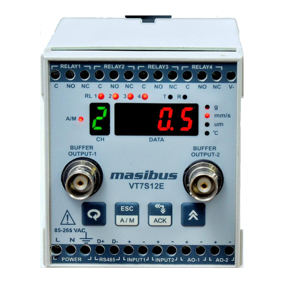
Page 8: Front Panel Description
VIBRATION TRANSMITTER-VT7S12E Ref No: mVTD/om/201 Issue No: 02 4. FRONT PANEL DESCRIPTION Figure 1 Front Panel Description Name of Part Function Displays Process Value. Process Value Display Parameter Name When You Set Parameter. Display(DATA window) Displays Error Message When An Error Occurs. -
Page 9: Connetion Diagram
VIBRATION TRANSMITTER-VT7S12E Ref No: mVTD/om/201 Issue No: 02 6. CONNETION DIAGRAM Figure 2 Connection Diagram of VT7S12E User’s Manual - 9 -... -
Page 10: Menu Layout
Ref No: mVTD/om/201 Issue No: 02 7. MENU LAYOUT 7.1 Flow Diagram Vibration Transmitter - VT7S12E has a number of software parameters which may or may not be required depending on your particular applications. Figure 3 Level-1 Flow Diagram User’s Manual... -
Page 11: Figure 4 Level-1, Level-2, Calibration & Factory Reset Mode Flow Diagram
VIBRATION TRANSMITTER-VT7S12E Ref No: mVTD/om/201 Issue No: 02 LVL2 LVL3 FrSt 0000 0000 0000 0000 0000 0000 0000 0000 inPt SkiP LdEF CALZ Pv-H rLLH CLAL CALS Pv-L rLGP CLAL rtrZ SCAn PArA rtrS Srno FLTR bAud rLLG Procedure for changing/setting... -
Page 12: Menu Parameters
VIBRATION TRANSMITTER-VT7S12E Ref No: mVTD/om/201 Issue No: 02 7.2 Menu Parameters Run Mode: Following parameters can view or change during run time. Immediately after powering, unit will run in Auto Mode. In auto mode channel will scan automatically according to scan time selection (1-250 second). -
Page 13: Relay Configuration
VIBRATION TRANSMITTER-VT7S12E Ref No: mVTD/om/201 Issue No: 02 Inp . t F o l l o w T a b l e 2 2 ( I n p u t t y p e f o r A c c e l e r a t i o n ( f o r a l l... -
Page 14: Table 8 Relay Group - 2 Configuration Detail
VIBRATION TRANSMITTER-VT7S12E Ref No: mVTD/om/201 Issue No: 02 If relay group – 2 is selected, there will be two group of relay. Each group has two relays. (G-1 and G-2). G-1 means relay 1, relay 3 & G-2 means relay 2, relay 4... -
Page 15: Table 11 Level - 3 Parameter Description
VIBRATION TRANSMITTER-VT7S12E Ref No: mVTD/om/201 Issue No: 02 yes / no Skip C h a n n e l s k i p / 0 : N O 0 ( f o r a l l c h a n n e l ) U n s k i p s e l e c t i o n . -
Page 16: Table 12 Ao (Analog Output)(Retransmission Output) Description
VIBRATION TRANSMITTER-VT7S12E Ref No: mVTD/om/201 Issue No: 02 Retransmission Output number Retransmission Output Setting Name and Description (Decimal) number (Hex) none 0 x 00 (None) Rt.01 0 x 01 (Retransmission Output-1) Rt.02 0 x 02 (Retransmission Output-2) Table 12 AO (Analog Output)(Retransmission Output) description Note: - By default For Channel-1 Retransmission output-1 and For Channel-2 Retransmission output- 2 is set. -
Page 17: Relay Outputs
(as per relay delay) and it will be ON until process value goes up toward Set point. NOTE:- VT7S12E has both Control Logic (ON-OFF) & Alarm Logic. If Control Logic (ON-OFF) is required, rloP in lvl2 must be selected as Co. - Page 18 VIBRATION TRANSMITTER-VT7S12E Ref No: mVTD/om/201 Issue No: 02 Alarm 1 Momemtary alarm (when in abnormal condition ack not pressed) CONDITION NORMAL ABNORMAL UP (O/S) DOWN (O/S) ACK ** NORMAL * ACK *** Lamp Steady Steady Steady Alarm Latch Relay Lamp...
- Page 19 VIBRATION TRANSMITTER-VT7S12E Ref No: mVTD/om/201 Issue No: 02 Alarm al1 Maintained alarm (when in abnormal condition ack is pressed) DOWN CONDITION NORMAL ABNORMAL UP (O/S) (O/S) ACK ** NORMAL * ACK *** Lamp Steady Steady Steady Steady Alarm Latch Relay...
- Page 20 VIBRATION TRANSMITTER-VT7S12E Ref No: mVTD/om/201 Issue No: 02 NOTE: * means normal condition after abnormal has occurred ** means ack pressed in abnormal condition *** means ack pressed in normal condition after abnormal has already occurred. **** means it remains in the previous state. If previous state is ON then it will remain ON and the same case for OFF condition.
-
Page 21: Calibration Procedure
Retransmission output calibration (Voltage/current output) (Optional):- In VT7S12E, maximum 2 numbers of Analog Output (Retransmission Output) are available. Analog output should be measured using a highly accurate digital multi meter. If user wants Current output then Output current value needs to be calibrated. For Current output calibration, set output type as 4-20 mA. -
Page 22: Modbus Communication Detail
VIBRATION TRANSMITTER-VT7S12E Ref No: mVTD/om/201 Issue No: 02 10. MODBUS COMMUNICATION DETAIL The MODBUS Communications protocol as RS-485 interface module is installed. Only RTU mode is supported. Data is transmitted as 8-bit binary bytes with 1 start bit, 1/2 stop bit and optional parity checking (None, Even, Odd). Baud rate may be set to 9600 and 19200. - Page 23 VIBRATION TRANSMITTER-VT7S12E Ref No: mVTD/om/201 Issue No: 02 Modbus Parameter Details for Input Register: SR.N Absolute Parameter Access Refer Parameter Max Value Address Type Value Type Table SP.1 CH – 1 40001 SP.1 CH – 2 40002 SP.1 CH – 3 40003 SP.1 CH –...
-
Page 24: Table 19 Modbus Parameter Details For Input Register
VIBRATION TRANSMITTER-VT7S12E Ref No: mVTD/om/201 Issue No: 02 SKIP-Channel CH - 2 40063 SKIP-Channel CH - 3 40064 SKIP-Channel CH - 4 40065 RLY Latch 40066 Table 33 RLY Group 40067 Table 27 Scan Rate 40068 Auto CJC 40069 Fix CJC 40070 60.0... -
Page 25: Table 21 Modbus Parameter Details For Read Output Status Register
VIBRATION TRANSMITTER-VT7S12E Ref No: mVTD/om/201 Issue No: 02 Alarm.2 Channel-3 Alarm.2 Channel-4 Alarm.3 Channel-1 Alarm.3 Channel-2 Alarm.3 Channel-3 Alarm.3 Channel-4 Alarm.4 Channel-1 Alarm.4 Channel-2 Alarm.4 Channel-3 Alarm.4 Channel-4 RELAY STATUS-1 RELAY STATUS-2 RELAY STATUS-3 RELAY STATUS-4 Auto/Manual Mode Acknowledge Status... -
Page 26: Table 27 Relay Group Selection
VIBRATION TRANSMITTER-VT7S12E Ref No: mVTD/om/201 Issue No: 02 Table 27 Table 28 Table 29 Table 30 Relay Group Relay Group 1 Relay Group 2 Relay Group 4 Selection Selection Selection Selection Modbus Parameter Modbus Parameter Modbus Parameter Modbus Parameter Index... -
Page 27: Miscellaneous
VIBRATION TRANSMITTER-VT7S12E Ref No: mVTD/om/201 Issue No: 02 11. MISCELLANEOUS PV INPUT STATUS DISPLAY DURING BURNOUT CONDITION: Input type Display Message Acceleration RMS OPEN Acceleration PEAK OPEN Acceleration OPEN PEAK-PEAK Velocity RMS OPEN Velocity PEAK OPEN Velocity PEAK-PEAK OPEN... -
Page 28: Table 41 Retransmission Output During Open/Over Condition
VIBRATION TRANSMITTER-VT7S12E Ref No: mVTD/om/201 Issue No: 02 RETRAMISSION OUTPUT TABLE FOR OPEN /OVER CONDITION : RETRASMISSION VARIABLE SCALE ACTION OPEN OVER ERROR 4-20 mA 21.6 20.8 DOWN 20.8 DOWN 20.8 Table 41 Retransmission Output during Open/Over Condition NOTE: - ... -
Page 29: Troubleshooting
VIBRATION TRANSMITTER-VT7S12E Ref No: mVTD/om/201 Issue No: 02 12. TROUBLESHOOTING If the operating display does not appear after turning on the Vibration Transmitter power, follow the measures in the procedure below. If a problem appears complicated, contact our sales representative.
Need help?
Do you have a question about the VT7S12E and is the answer not in the manual?
Questions and answers