
Related Manuals for VPInstruments VPFlowScope VPS.R080.M050 series


Summary of Contents for VPInstruments VPFlowScope VPS.R080.M050 series
- Page 1 VPINSTRUMENTS.COM VPFlowScope in-line User manual © 2017 Van Putten Instruments BV MAN-VP-SINL-UK-1701 Date:22-03-2017...
- Page 2 VPFlowScope in-line © 2017 Van Putten Instruments BV All rights reserved. No parts of this document may be reproduced in any form or by any means - graphic, electronic, or mechanical, including photocopying, recording, taping, or information storage and retrieval systems - without the written permission of the publisher.
-
Page 3: Table Of Contents
Contents Table of Contents 1 Warning - Read this first 2 Introduction 3 Product overview 1 Configuration ........................... 7 2 VPFlowScope in-line D0 (no display) ........................... 8 3 VPFlowScope in-line D10 & D11 (display version) ........................... 8 4 VPFlowScope in-line D0 with the VPFlowTerminal ........................... - Page 4 VPFlowScope in-line 3 Service subscriptions ........................... 28 11 Specifications 12 Order information and accessories 13 Appendix A - UL © 2017 Van Putten Instruments BV | MAN-VP-SINL-UK | Revision:1701 | Date:22-03-2017...
-
Page 5: Warning - Read This First
Not intended for fiscal metering or billing. Our flow meters are not certified for fiscal metering. Laws on fiscal metering and billing may vary per country or state. Do not overestimate the results. VPInstruments does not take any responsibility for the correctness of measurement results under field conditions. -
Page 6: Introduction
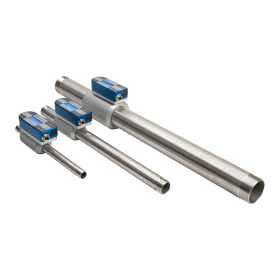
VPFlowScope in-line Introduction Congratulations! You purchased the easiest to use and most complete compressed air measurement tool in the world. With the VPFlowScope in-line, you can monitor and record flow, pressure, temperature, and total air consumption, simultaneously. Great products deserve great user manuals. We have done our best to make this user manual as complete as possible. -
Page 7: Product Overview
The instruments are pre programmed and ready to use. For configuration of the outputs and data logger, the VPStudio configuration software is used. This software can be downloaded from our website. www.vpinstruments.com/downloads © 2017 Van Putten Instruments BV | MAN-VP-SINL-UK | Revision:1701 | Date:22-03-2017... -
Page 8: Vpflowscope In-Line D0 (No Display)
VPFlowScope in-line VPFlowScope in-line D0 (no display) The D0 model can be used in applications where local read-out and data logging is not required. With it's various outputs the VPFlowScope in-line can be connected to remote data loggers. VPFlowScope in-line D10 & D11 (display version) The D10 and D11 models add a 3 row display with keypad to the VPFlowScope in-line. -
Page 9: Quick Start
Quick start This chapter contains the basic steps to start using your VPFlowScope in-line flow meter. Additional information on all subjects can be found in the next chapters. 1. Unpack Unpack the meter and check if all items are there and in good shape. A checklist with all items is available on the box. -
Page 10: Measurement
VPFlowScope in-line Measurement For all parameters the update interval is 1 second. Within this second, multiple samples are taken and averaged to provide a stable and reliable output. Flow The VPFlowScope in-line uses our proprietary insertion type thermal mass flow sensor. There is no bypass flow, which results in a high robustness and less sensitivity for dirt or particles. -
Page 11: Totalizer
Totalizer The totalizer keeps track of the total consumed amount of compressed air in normal cubic meters, or in scf depending on which unit you choose to read out. The refresh interval is 1 second, actual measurement data will be available on the display and by Modbus. For back up reasons, the totalizer value is written to it's internal memory with an interval of 15 minutes. -
Page 12: Mechanical Installation
In very complex situations, with multiple up- and downstream objects, you should consider another location. This table is a practical guideline and is not exact science. Practical situations can have multiple sources of distortion, therefore VPInstruments does not take any responsibility for the correctness. -
Page 13: Installation Without Tubing Kit
Upstream Downstream Picture Description Effect length length Single elbow 30 * D1 10 * D1 Distorted flow profile Complex feed-in situation 40 * D1 10 * D1 Flow profile will be (header) distorted Double elbow, multiple 40 * D1 10 * D1 Distorted profile + elbows following each swirl... - Page 14 VPFlowScope in-line Check the pipework and the O-rings, which are pre-mounted on the pipes. Apply a little O-ring grease to ease the mounting process. Screw both pipes into the VPFlowScope in-line. Gently screw the pipes into the flow meter inlet. Turn it all the way in, until the end of the pipe reaches the bottom of the inlet hole You can install the VPFlowScope in-line directly between two threaded pipe ends.
-
Page 15: Display
Display The display provide some additional features: · LCD display with 3 rows of real time data, refreshed every second · Key pad with menu to configure the main settings · Data logger with adjustable logging intervals (option) · 5 custom units (multiply and existing unit with a factor and show it on the LCD display) Display status icons Some status icons show feedback on the meters' status. -
Page 16: Keypad
VPFlowScope in-line Multiple sessions can be recorded. When a session is started, a separate session will be recorded. It's not possible to append to an existing session. When a power failure occurs during recording, the session will be stopped. When power is restored, a new session will start automatically. - Page 17 1 Settings The settings menu can be used to change both functional parameters as display settings. 1.1 Display The main screen of the display contains 3 rows to display measurement values. Via this menu measurement values can be assigned to these rows. Available options in the menu are: Measurand Available units Description...
- Page 18 VPFlowScope in-line 2 DAQ Sessions The VPFlowScope in-line contains an optional 2 Million point data logger. When available, the menu is set to start and stop the sessions or to delete all present data. 2.1 Start session The session will be started when you push the enter button after selecting this option. When the session is started, the menu will close and the main screen will be shown.
-
Page 19: Vpstudio Software
VPStudio software The VPFlowScope in-line can be read out and configured with the VPStudio software. This software can be downloaded from www.vpinstruments.com. In case of basic configuration and read out, use the free edition. If real time logging is required, request a license code by our sales department. -
Page 20: Electrical Connections
RS485 B Black RS485 A Grey * Wire colors for standard VPInstruments cables M12 5-pin female connector Cabling Shielded twisted pair cabling must be used for proper communication and measurement. Connect shield to safety ground on one point. The thickness of the wires depends on the cable length. For cabling below 300 meter | 1000 ft, use 20 awg. - Page 21 For scaling purposes, the zero and span matching 4 and 20mA can be modified. This will not effect the original measurement range. The zero and span are only used to increase or narrow the resolution. For bi-directional measurement, the zero value needs to be set negative. See below table for factory defaults.
-
Page 22: Pulse Output
VPFlowScope in-line Electrical scheme: The current meter is placed in between the current output and the power supply ground. You can also use a digital multimeter to test the current output. Pulse output The VPFlowScope in-line features a low-frequency active pulse output. The pulse is a ‘non potential’ free output as it acts like a controlled current output. -
Page 23: Modbus Interface
Pulse output Electrical scheme: Modbus interface Introduction to Modbus For a complete introduction on the Modbus standard can be found on www.modbus.org. See the document Modbus_over_serial_line_V1_02.pdf, which can be downloaded from their website. We strongly recommend to download and read this information carefully before installing Modbus communication. - Page 24 VPFlowScope in-line Register map The actual measurement data is placed in holding registers. To read out data, you will need to use the corresponding holding register. All data is stored in 2 16-bit registers with below register number as start address. Read out the data with this start address and length 2. Decimal Description Type...
- Page 25 Available write operations Option Data Description 4..20mA unit /sec /min SCFM /min sfps °C Other °F /sec 4..20mA min Decimal value 4..20mA max Decimal value Totalizer Integer or floating point type Will reset the totalizer to zero depending on register type Installing a RS485 network require specific knowledge.
- Page 26 (typically, 120 ohms for twisted pairs). There can only be one termination resistor at the very end of the trunk line. The VPInstruments junction box features a jumper that can be used to enable a 120 Ohm resistor. When using the VPInstruments Modbus Junction boxes make sure that the 120 Ohm resistor is only enabled in the last Modbus Junction box in the daisy chain.
-
Page 27: Usb Interface
USB interface The VPFlowScope in-line D10 and D11 model offer a built-in USB interface for configuration and data log session retrieval. The USB interface is protected by an IP65 rated nylon cap. IMPORTANT: the IP65 rating may be compromised when this cap is damaged or not placed back in a proper manner. To ensure proper sealing, the cap must be greased with a little o-ring grease or vaseline grease. -
Page 28: Service
10.1 Software and firmware updates News on software and firmware updates can be found on www.vpinstruments.com, or are provided by your local re-seller. The VPFlowScope in-line sensor can be updated via the RS485 port. The USB interface is used for updating the firmware of the display. Instructions on the update procedure can be found in a separate instruction leaflet, which is distributed on request. -
Page 29: Specifications
Specifications Please always check the label of your product for the specifications. Specifications are subject to change as we are continuously improving our products. Please contact us to obtain the latest specification sheet. Flow sensor (minimum detection level and max flow rate shown) - VPS.R080.M050 0.13…50 SCFM 0.23...80 m... -
Page 30: Order Information And Accessories
VPFlowScope in-line Order information and accessories Order Code Flow range Option Display Option Connector VPS.R080.M050 0 ... 80 m 3 No display 5 Pin M12 VPS.R250.M100 0 ... 250 m 3 Display 8 Pin M12, for remote n /hr display * VPS.R01K.M200 0 ... -
Page 31: Appendix A - Ul
Appendix A - UL The VPFlowScope complies with the CE requirements as stated in the CE declaration. CE compliance can only be achieved when grounding and shielding directions are followed and proper cables and connector assemblies are used. Electrical connection guidelines- UL 508 Listing for USA & Canada (Check label to see if product is UL marked) The VPFlowScope is intended to be used with a Class 2 power source or Class 2 transformer in accordance with UL1310 or UL1585. - Page 32 VPFlowScope in-line Notes © 2017 Van Putten Instruments BV...
- Page 33 EASY INSIGHT IN ENERGY FLOWS VPInstruments Buitenwatersloot 335 2614 GS Delft The Netherlands info@vpinstruments.com www.vpinstruments.com MAN-VP-SINL-UK-1701 Date: 22-03-2017...
Need help?
Do you have a question about the VPFlowScope VPS.R080.M050 series and is the answer not in the manual?
Questions and answers