mcmurdo NAV-7 Service Manual
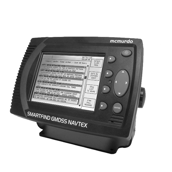
Gmdss tri-channel navtex receiver
Hide thumbs
Also See for NAV-7:
- User & installation manual (52 pages) ,
- User & installation manual (26 pages)

Related Manuals for mcmurdo NAV-7


Summary of Contents for mcmurdo NAV-7
- Page 1 NAV-7 GMDSS Tri GMDSS Tri GMDSS Tri GMDSS Tri- - - - channel NAVTEX Receiver channel NAVTEX Receiver channel NAVTEX Receiver channel NAVTEX Receiver Service Manual Service Manual Service Manual Service Manual...
-
Page 3: Table Of Contents
All rights are strictly reserved. The information must not be used except for the agreed purpose. Unauthorised use, reproduction or issue to any third party is not permitted without the prior written authority of McMurdo Limited. This document is to be returned to McMurdo Limited when the agreed purpose is fulfilled. Page 1... -
Page 4: Commercial In Confidence 35-506 Iss
Commercial in confidence 35-506 Iss 1 Page 2 NAV-7 service manual... -
Page 5: Introduction
It will display reliable information day after day within designated NAVTEX coverage areas. Installation is straightforward. Connect the NAV-7 to a 12 or 24 volt DC supply and connect a suitable antenna. Switch it on, and it will start displaying and storing NAVTEX messages without further manual intervention. -
Page 6: Scope
Commercial in confidence 35-506 Iss 1 The NAV-7 can be setup to filter out stations and/or message categories that are not required by the User. The NAV-7 is capable of being connected to an Integrated Bridge System (IBS), transferring NAVTEX messages to other navigational aids if required. Note that the IBS must be compliant with the serial port requirements of IEC61097-6 (Ed 2.0). -
Page 7: Safety Notices
Make sure that the working area is well ventilated, and that chemical substances are not left exposed. Observe good hygiene practices; do not eat, drink or smoke when handling chemicals. Read the manufacturer's instructions before using any chemical agent. Wear goggles Wear overalls Wash hands Wear gloves Page 5 NAV-7 Service Manual... - Page 8 Commercial in confidence 35-506 Iss 1 Page 6 NAV-7 service manual...
-
Page 9: Assessment
Alarm events are sent over the data interface output port(s) using the ALR sentence format. Whatever the reason for the return the NAV-7 must be subjected to a full assessment before any other action is taken. The agent has a responsibility to ensure the NAV-7 is completely serviceable and is fit for its purpose. -
Page 10: Assessment
Commercial in confidence 35-506 Iss 1 2.3. Assessment Every NAV-7 returned for servicing, of whatever nature, must be fully assessed to determine its operational status. Assessment form The assessment form, shown on the next page, is an essential tool in performing diagnosis. - Page 11 Main unit Antenna/bracket Power cable Manual Diagnosis/Comments FUNCTIONAL TEST ATE (in factory only) Functional Test Burn-in Comments Conclusions New Parts Fitted RF PCB Keypad LCB screen Display PCB Gasket Assessed by Signed Date Backbox Pass Fail Page 9 NAV-7 Service Manual...
-
Page 12: Maintenance Procedures
35-506 Iss 1 3. MAINTENANCE PROCEDURES 3.1. Inspection The NAV-7 should be inspected prior to any servicing/repair work. The following should be inspected: • Case – ensure no cracks in the plastic or other damage. • Screen – Inspect display if possible to ensure not damaged. - Page 13 Commercial in Confidence 35-506 Iss 1 Page 11 NAV-7 Service Manual...
-
Page 14: Disassembly
Warning: the backlight for the display is powered by 250V AC. A clean room may be required when replacing the screen. Back Box removal 1. Remove the 6 off self tapping screws 2. Lift off the back box and disconnect the ribbon cable. Page 12 NAV-7 service manual... - Page 15 1. Remove the 3 off screws from the PCB. Note that the one screw may be secured into a pillar and so will be of a different type. 2. Remove the 4 off connector clamps (see above) using 5mm socket or nut runner. Connector clamps Page 13 NAV-7 Service Manual...
- Page 16 Commercial in confidence 35-506 Iss 1 Ensure that pillar (if fitted) is tight before reassembly. Page 14 NAV-7 service manual...
- Page 17 35-506 Iss 1 Display PCB removal 1. Remove the 11 OFF self tapping screws. 2. Disconnect the backlight power supply cable to the display. Note that there is 250V AC on this cable when powered up. Page 15 NAV-7 Service Manual...
- Page 18 Commercial in confidence 35-506 Iss 1 3. Remove the silver tape link. It is recommended that this is not reused. 4. Release the lock and disconnect the ribbon connector. Page 16 NAV-7 service manual...
- Page 19 1. Remove the keypad – this lifts out. 2. Remove the 4 off screws retaining the display. 3. The display can now be lifted out. The fascia/window assembly is supplied complete – if it is damaged please order a replacement assembly. Page 17 NAV-7 Service Manual...
-
Page 20: Reassembly
Refit Display PCB 1. Replace PCB on top fascia and reconnect the ribbon connector – ensure the locking mechanism is secure. 2. Reconnect the backlight. 3. Refit 2 off screws to 50cNm as per below: Page 18 NAV-7 service manual... - Page 21 2. Fit 4 off Connector clamps with screwlock (Loctite) and secure to 40cNm. 3. Refit back box gasket. 4. Reconnect the ribbon cable. 5. Place back box in position, ensure gasket is in position and secure with 6 off screws to 40cNm. Page 19 NAV-7 Service Manual...
-
Page 22: Leak Testing
Commercial in confidence 35-506 Iss 1 3.5. Leak Testing The NAV-7 is not a sealed unit. Therefore there is no requirement to leak test the product. However if the unit is flush mounted then the front fascia is approved to IEC60945-4 for Protected equipment. -
Page 23: Factory Reset
If the SERVICE password has been changed for any reason and the new password is not known then please use TWINKY89. Once entered there will be a double spanner ICON at the top of the screen. This will remain until the power is cycled. Page 21 NAV-7 Service Manual... -
Page 24: Software Download
• Cable to connect to 9 way D-type on the back of the NAV-7. • A power supply connected to the 15 way connector on the back of the NAV-7. Copy the zip file (NAV-7 release *.zip) into a suitable directory. -
Page 25: Fault Finding
Ensure that the 1/8 ” spade terminal ground pin at the of the NAV-7 is connected to a good electrical ground. This should be the ship’s hull or can either be a specially installed ground plate, or the keel bolts on a non-encapsulated keel or bonded hull skin fitting. -
Page 26: Fault Location
1. Is there s/w in the unit? Try to re-load the software 2. Does the red LED flash? If not swap the display PCB Backlight failed 1. Check for trapped Cold cathode fluorescent light (CCFL) wires 2. Swap the LCD module 3. Swap the display PCB. Page 24 NAV-7 service manual... -
Page 27: Service Bulletin 08
(IBS) messages (NRX etc). The ports are set up in SET UP MODE: SERIAL OPTIONS. Example 1: If the NAV-7 needs to be connected to an older style IBS that does not handle NAVTEX messages. Set the NMEA Port speed as required. Set the printer width as required. -
Page 29: Repair Procedures
Full instructions for this can be found in section 3.0 Disassembly and Reassembly. Other than this, repair is limited to replacing those parts of theNAV-7 which have suffered mechanical wear and tear. Spare parts for these purposes are listed in section 6. Page 27 NAV-7 service manual... -
Page 30: Spares
Bracket, locking knobs, screws Deskmount bracket kit 89-113-001 Bracket, locking knobs, screws Earth cable 35-801 Active Antenna ACT-1 AC/DC Power supply 89-029 User manual 35-821 Available on website Front fascia 35-115 Fascia and screen. 2m Interface cable 35-800 Page 28 NAV-7 service manual... -
Page 31: Appendix 1 : Specification
Conforms to IEC 61162-2 8 data, 1 stop, no parity Baud rates 4800, 38400, 115200 Supports (in priority order) RMC, GLL, ZDA for date and time Supports NRX, NRQ, NMK, ACK, ALR for NAVTEX functions NAV-7 service manual Page 29... - Page 32 Voltage range 12/24 V DC nominal (10.8 V to 31.2 V) Consumption, backlight dimmed 5.7 W @ 24 V DC Consumption, backlight full on 8.6 W @ 24 V DC Fused internally 1.8 A resettable type NAV-7 Service manual Page 30...
- Page 33 Commercial in confidence 35-506 Iss 1 NAV-7 service manual Page 31...
- Page 34 McMurdo Silver Point Airport Service Road Portsmouth PO3 5PB United Kingdom Phone: +44 (0)23 9262 3900 Fax: +44 (0)23 9262 3998 Email: customerservice@mcmurdo.co.uk Website: www.mcmurdo.co.uk 35-506 Issue 1...
Need help?
Do you have a question about the NAV-7 and is the answer not in the manual?
Questions and answers