Advertisement
Table of Contents
- 1 Table of Contents
- 2 Overview of this Machine
- 3 Before Use
- 4 Operating Precautions
- 5 Names of Machine Parts
- 6 Adjustments and Checks before Use
- 7 Maintenance
- 8 Parts Adjustments and Replacements
- 9 External Output Signals
- 10 Miscellaneous
- 11 Troubleshooting
- 12 Specifications
- 13 External Dimensions
- 14 Warranty
- Download this manual
Automatic Screw Feeder
QUICHER
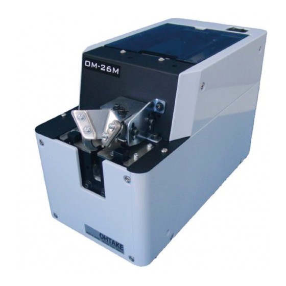
OM-26M
NSRI Type
Operation Manual
Operation Manual
Read these instructions for the proper use of this machine.
・ Read these instructions for the proper use of this machine.
After having read these instructions, keep them in a convenient place so you
・ After having read these instructions, keep them in a convenient
or the operator can refer to them whenever necessary.
place so you or the operator can refer to them whenever necessary.
ATTENTION : www.ohtake-root.co.jp is the only web site associated with our company.
We do not have any branches in China.
www.ohtake-root.co.jp
www.ohtake-root.co.jp
Automatic Screw Feeder
Type
(Maintenance)
HP
自動ネジ供給機
OMM1MA02 M
NSIR MAE01
Advertisement
Table of Contents

Subscribe to Our Youtube Channel
Summary of Contents for OHTAKE OM-26M
- Page 1 ATTENTION : www.ohtake-root.co.jp is the only web site associated with our company. We do not have any branches in China.
-
Page 2: Table Of Contents
7. PARTS ADJUSTMENTS AND REPLACEMENTS ----- 16 1.OVERVIEW OF THIS MACHINE Thank you very much for selecting our Automatic Screw Feeder "OM-26M series ". This machine can line up screws (Type M2 - M6) and supplies them one by one to help the efficiency of screw fastening work. -
Page 3: Operating Precautions
3.OPERATING PRECAUTIONS This manual contains safety alert symbols and signal words to help prevent injuries to the user or damage to property. ◎ Indications This indicates there is a chance of death, serious injury or fire if the instructions WARNING are not followed. - Page 4 WARNING Do not disassemble the AC adapter as there is a risk of electric shock, fire or malfunction. Do not damage, alter or change the power cord. Do not place heavy objects on the cord. Do not pull hard on the cord or twist the cord as it could be damaged, thereby causing a risk of fire or electric shock.
- Page 5 CAUTION Use only the AC adpater supplied with this machine otherwise it may result in a fire or electric shock. Do not install this machine in an unstable location otherwise it may fall causing damage or injury. Always operate the machine with the upper cover in place, otherwise it may result in injury. Do not allow any foreign material to enter the machine while in operation.
-
Page 6: Names Of Machine Parts
4.NAMES OF MACHINE PARTS Power switch Top lid Rail fixing bolt Bit guide bracket Bit guide bracket Holding plate attaching plate Front cover Left guide Bit guide LED screw indicator Right guide Front lower cover Holding plate adjusting bolt Light-emitting Light-receiving sensor Holding plate... - Page 7 Rear cover Scraper-left Scooping hopper Brush Scraper-right Rail assembly Frequency adjusting knob Amplitude adjusting knob Timer adjusting knob Signal line out Passing plate DC jack - 6 -...
-
Page 8: Adjustments And Checks Before Use
5.ADJUSTMENTS AND CHECKS BEFORE USE 5-1.Checking the model number of the main body Identification stamp Check if the machine has the parts which match the nominal diameter of the screws to be loaded. Check the model number of the rail, escaper, stopper assembly, escaper guide-right, and passing plate by referring to the following table. - Page 9 5-2.Basic operations ○Loading the screws ・Turn the power switch ON and OFF so that the brush stops vertically above the rail. ・Open the top cover and load screws on the left and right side of the rail evenly. ・Do not load screws above the surface of the rail. ・Be sure to determine the screw load by observing the machine while it is in operation.
- Page 10 ○Pick uping Screws ① Put the screwdriver ・Pick up the screws at the stopper with the electric screw driver. ① d o w n v e r t i c a l l y a s Use the bit guide to put the screwdriver down vertically into the screwhead's slots, twisting it slightly and insert the bit into the then pull the screwdriver, horizontally, towards you as pick uping the screw.
- Page 11 5-3.Adjusting the brush height Turn On and Off the power switch to put the brush Turn OFF the power switch before starting replacement and bristles in a horizontal position towards the left side. adjustment. Load the screws into the scooping hopper, turn ON and OFF the power switch so that screws are alligned into the rail groove.
- Page 12 5-4.Checking and adjusting the rail vibration The amplitude and frequency of the rail vibration can be adjusted. Frequency adjusting knob The vibration has been adjusted at the factory for screws that correspond with the rail. High Put some screws into the rail and turn the power on. If they are delivered smoothly, there is no need for adjustment.
- Page 13 5-5.Check and adjust the front and rear sides of the rail Rail fixing bolt Turn OFF the power switch before starting replacement and adjustment. ・If the rail comes into contact with the escaper, or the clearance between the rail and escaper is too large, loosen the rail fixing bolt, hold the rail groove and adjust the rail assembly either backward or forward.
- Page 14 5-7.Check and adjust the passing plate Turn OFF the power switch before starting replacement and adjustment. ・Check that the passing plate is adjusted to a height that permits loaded screws to pass just within the limit. Passing plate ・If the passing plate is too low, screws cannot pass. attaching bolt If the passing plate is too high, it will hamper a smooth transport of the Passing plate...
- Page 15 5-9.Check and adjust the timer The screw transport feed differs depending on screw type. This machine can make screw unloading smooth through timer adjustment. For screws with a low transport speed, set the timer long. For screws with a high transport speed, set the timer short.
- Page 16 5-11.Checking and adjusting the bit guide ・Adjust the bit guide's height by loosening the attaching bolts. ・Take care that the bit guide does not contact the screw heads. ・Use the screwdriver and Allen wrench that come with this machine. Remember to tighten the bolts and screws after adjustment. ・After adjustment, check that the pick up of screws is smooth.
-
Page 17: Maintenance
6.MAINTENANCE A dirty rail groove may interfere with the screw transport speed. Clean the dirty rail with a soft, clean cloth dipped in alcohol. If cleaning is difficult, remove the rail from the machine and clean the rail groove. Refer to the next section under『7-1 Replacing the rail assembly』 for replacing. Before removing the rail from the machine, be sure to turn off the power supply and take the screws out of the hopper. - Page 18 7-1.Replacing the rail assembly Remove the Turn OFF the power switch before starting replacement and bit guide assembly. adjustment. Before replacing, remove all the screws from the hopper, the rail, and the escaper. The rail assembly of this machine can be easily replaced. If there is any dirt or flaw on the rail groove that prevents a smooth ①...
- Page 19 7-2.Replacing and adjustment of the escaper Names of the parts Turn OFF the power switch before replacing. Holding plate Spacer fixing screw Spacer Turn ON the power switch when adjustments are necessary. Escaper guide-right Before replacing, remove all the screws from the hopper, the Stopper rail, and the escaper.
- Page 20 Loosen the spacer fixing screw and remove the spacer. Remove the spacer. Remove the screw under the stopper and remove the stopper Remove the stopper assembly. assembly. ② Attach the escaper guide-right, escaper and stopper assembly that corresponds with the screw's nominal diameter. Stopper First, attach the stopper assembly.
- Page 21 Position the spring arm under the Position one of the spring arms under the plain washer plain washer of the spacer screw. of the spacer screw and the other arm on the stopper tab. Attach the escaper and the escaper guide-right. The stopper should Assemble the escaper loosely as it will need adjusting later.
- Page 22 ④ Check the position of the parts for smooth delivery of the screws. Check that the clearances between the outside edges of the rail and the escaper guide-right and left are almost even. If they are in contact, the screws cannot be delivered. If there is too much clearance, on either side, screws may fall into the machine.
- Page 23 7-3.Checking and adjusting the sensor Front sensor Attach while ajusting the height Usually, there is no need to adjust the sensor as it was done when assembled in the factory. Front sensor The following are irregular situations that require adjustment: bracket attaching -There is no screw at the pick up spot but, the LED is on and the escaper screw...
- Page 24 7- 4.Replacing the Passing Plate Passing plate attaching screw Turn OFF the power switch before starting replacement and Passing plate adjustment. Use the passing plate, rail and escaper that correspond with the di- ameter of the screws to be used. Remove the passing plate.
- Page 25 7-6.Replacing the driving belt Turn OFF the power switch before starting replacement and adjustment. If the driving belt is worn, cut or slips while in use, replace it with a new one. ・Turn the power OFF and remove all covers. ・Remove the driving belt from the pulley by using a screwdriver to pry it off.
- Page 26 7-7.Replacing the Main Motor Turn OFF the power switch before starting replacement and R e m o v e t h e f r o n t adjustment. c o v e r a n d t h e L E D connector.
- Page 27 ⑤ Using the accompanying hex wrench, loosen the 2 hex head bolts from the driving pulley and remove it. If the bolts are hard to access, rotate the motor pulley with the hex wrench. ⑥ Remove the motor attaching screws. ⑤...
- Page 28 .Replacing the stopper Spring end nut Turn OFF the power switch before replacing. Spring holder The stopper is a consumable part. When the stopper is worn-off or Stopper spring damaged in shape, replacement is necessary to ensure proper machine operations. (When stopper is being replaced, the escaper guide does not need to be removed from the machine.)...
-
Page 29: External Output Signals
8. EXTERNAL OUTPUT SIGNALS 8 - 1.External Output Signals Remove the front cover This machine can take out the screw extraction signal. Please use and the LED connector. it for connection with general purpose sounter etc. Since the signal line is stored inside, when using it please remove the main body cover and pull out the signal line from the outlet hole. - Page 30 [Function]: Screw present: signal high (ON) Outseide of the feeder Example of connection Incoming current: shall be limited to less than Inseide of the feeder 100mA **CAUTION: Additional resistor is required on Purple wire external circuit for regulating current ** [Capacity]: Max DC current: 100mA Gray wire CN10...
-
Page 31: Miscellaneous
9. MISCELLANEOUS Screw onto the top lid. 9 - 1.Screw quantity monitoring sensor (Optional) There is, as an optional attachment, a sensor which monitors the quantity of Put the harness through the notch screws remaining in the scooping hopper. at the back of the top lid. With this attachment connected to the signal line, you can set the sensor to monitor the level of screws remaining in the hopper. - Page 32 9 - 2.Overload protective circuit This machine is equipped with an overload protective circuit. Normally, the driving motor rotates forward to feed screws to the escaper continuously. However, if there is an overload at the driving section, the driving motor rotates backward for a certain amount of time and then returns to normal rotation.
-
Page 33: Troubleshooting
10.TROUBLESHOOTING For safety, always unplug the AC adapter from the wall outlet before making any adjustments. Trouble Cause Corrective measures The machine does not operate though ・Power is not supplied. ・Check the connection of the power the power switch is turned ON. supply of the AC power adapter. - Page 34 Trouble Cause Corrective Measure Screws do not flow. ・Screws in an abnormal position in the ・Adjust the brush. passing plate cannot be swept away ・Adjust the passing plate. with the brush. If a proper amount of screws are loaded into the scooping hopper, the status may be improved.
- Page 35 Trouble Cause Corrective Measure A s c r e w h a s f a l l e n i n t o t h e r a i l ・Screws with a smaller diameter than the ・Use screws with the specified nominal groove.
- Page 36 Trouble Cause Corrective Measure Screws tend to pass ・The passing plate is not adjusted ・Adjust the passing plate. through the passing plate in an ab- properly. normal position. The axis of the screw thread tends to ・Too many screws are in the scooping ・Reduce the quantity of screws to enter the passing plate.
- Page 37 Trouble Cause Corrective Measure The scooping operation does not ・The timer knob is not properly adjusted. ・Readjust the timer knob. stop though a screw is at the pick up site. The escaper operation does not stop ・The sensor does not detect a screw. ・Readjust the voltage of the sensor.
- Page 38 Trouble Cause Corrective Measure The escaper does not rotate when ・ Undesired objects blocking front screw ・ Make sure there are no debris or no screws are present, although the sensor. other indicator light is on. objects present in the sensor brackets. ・...
-
Page 39: Specifications
11.SPECIFICATIONS [CAUTION] Input:AC100~240V 50/60Hz ・This machine accepts only steel screws. Plastic or stainless screws cannnot Output:DC15V 1A (switching type) be used. 119(W) × 226(D) × 152(H) (mm) ・Check if the axis diameter of the loaded screw matches the rail groove width. ・Within The range of screw size and length below,there may be instances of Approx. - Page 40 ※ -In the Exchange kit ordered, Rail assembly, Escaper, Stopper diameter(φ ) (φ ) (φ ) (m assembly, Escaper guide-right φ φ 1.9~2.1 2.4~6 2.4~10 0.35 and Passing plate are included. φ φ 2.2~2.4 2.7~6 2.7~10 0.35 φ φ -Please contact us by “ ~ SET” 2.5~2.7 3.0~6 3.0~10...
-
Page 41: External Dimensions
12. EXTERNAL DIMENSIONS DC jack Unit : mm ※ Height to top of e scaper - 40 -... -
Page 42: Warranty
13. WARRANTY For users within Japan, the effective term of warranty is 6 months after delivery. Such warranty will not be applicable to purchases or users outside of Japan. If any troubles should occur, please contact your dealer. After the warranty period, repair services will be completed. In the following cases, the purchaser shall pay for parts and labor regardless of the terms of warranty: ... - Page 43 - 42 -...
- Page 44 Fax +81-191-24-3145 Fax +81-191-24-3145 「Quicher」 「OHTAKE」 「OHTAKE ・ ROOT KOGYO」 are trademarks or/and registered trademarks of OHTAKE ・ ROOT KOGYO CO.LTD. 「Quicher( クイッチャー)」 「OHTAKE」 「OHTAKE ・ ROOT KOGYO」 は、 株式会社 大武 ・ ルート工業の商標又は登録商標です。 The specifications and/or design may be altered, without notice, whenever there are changes or improvements.
Need help?
Do you have a question about the OM-26M and is the answer not in the manual?
Questions and answers