
Summary of Contents for Pure Sine Wave Generators DG-3500
-
Page 1: Operating Instructions
Digital Inverter Generator DG-3500 OPERATING INSTRUCTIONS PLEASE READ THIS MANUAL CAREFULLY BEFORE USING MACHINE... - Page 2 PREFACE Thank you for using our generator. This manual includes the operation and maintenance of DG-3500 All information in this publication is based on the latest product information available at the time of approval for printing. We reserve the right to make changes at any time without notice and without incurring and obligation.
-
Page 3: Safety Instruction
. Safety Instruction Ⅰ WARNING ◆ The generator is designed to give safe and dependable service if operated according to instructions. Read and understand this manual carefully before operating the generator or it may cause serious injury and equipment damage. WARNING ◆... - Page 4 WARNING ◆ Gasoline is extremely flammable and is explosive under certain conditions. Refuel in a ventilated area with engine stopped. ◆Keep away from cigarette, smoke and sparks when refueling the generator. Always refuel in a well-ventilated location. WARNING ◆ Connection for standby power to a building electrical system must be made by a qualified electrician.
- Page 5 CONENT DG-3500...
-
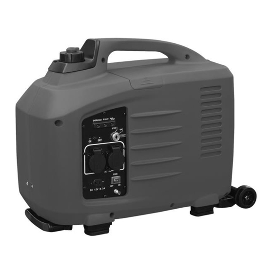
Page 6: Component Identification
DIGITAL INVERTER GENERATOR 3500W Warning Read this manual carefully before using the machine, for your own safety. Your power tool should only be passed on with these instructions. 1 COMPONENT IDENTIFICATION 1. Fuel cap 9. Overload indicator light 2. Air vent knob 10. - Page 7 Control panel Smart Throttle Engine speed is kept at idle automatically when the electrical appliance is disconnected and it returns to the proper speed to power of the electrical load when electrical appliance is connected. This position is recommended to minimize the fuel consumption while in operation.
-
Page 8: Safety Label Locations
3. SAFETY LABEL LOCATIONS These labels warn you for potential hazards that can cause serious injury. Read the labels and safety notes and precautions described in the manual carefully. If a label comes off or becomes hard to read, contact your dealer for a replacement. PRE-OPERATION CHECK Be sure to check the generator on a level surface with the engine stopped. - Page 9 Use high-detergent, premium quality 4 –stroke engine oil, certified to meet or exceed U.S. automobile manufacturer’s requirements for API Service Classification SG. SF.(15W40) Select the appropriate viscosity for the average temperature in your area. Ambient Temperature Loosen the cover screw and remove the left side maintenance cover. Remove the oil filer cap, and wipe the dipstick with a clean rag.
- Page 10 4.2 Check the fuel level Turn the fuel cap lever to “OFF” position before transporting. Use automotive fuel (Unleaded or low leaded is preferred to minimize combustion chamber deposits). !! Don’t use fuel-containing alcohol: Fuel system damage or engine performance problems resulting from the use of fuels that contain alcohol are not covered under the warranty.
-
Page 11: Generator Use
Never run the engine without the air cleaner. Rapid engine wear will result from contaminants. Such as dust and dirt, being drawn through the carburetor, into the engine. It is normal for a little oil to appear under the air filter box if the generator is running for a long period of time, or a lot of oil is in the engine. - Page 12 3. To start a cold motor shove the choke lever all the way to the left. To restart a hot motor set the choke lever halfway. Choosing the right choke position is the key to starting the motor. You may have to practice a few times to use the choke correctly.
- Page 13 6. After the engine starts, allow the engine to run continuously and warm up. 7. Press the choke in completely after the engine is started. If the engine stops and will not restart, check the engine oil level before troubleshooting in other areas. Move to the right to deactivate Before using the device once it is connected, switch off the ECO switch.
- Page 14 5.3 Generator use 5.3.1 Warning! ■To prevent electrical shock from faulty appliances , the generator should be grounded. Connect an electric conductor (cable) of at least 1.5mm between the generator’s ground terminal and an external ground source. ■Connections for standby power to a building’s electrical system must be made by a qualified electrician and must comply with all applicable laws and electrical codes.
- Page 15 5.5 Output and Overload indicators. The output indicator light (green) will remain lighted during normal operating conditions. If the generator is overloaded or of here is a short in the connected appliance, the output indicator light (green) will go OFF, the overload indicator light (red) will go ON and current to the connected appliance will be shut off.
- Page 16 When the output indicator light (green) does not light and the overload indicator light (red) lights instead, set the engine switch to STOP, stop the engine at once and then start the engine again. 3. Confirm that the equipment to be used is switched off, and insert the plug of the equipment to be used into the AC receptacle unit A.
- Page 17 ·When using the DC output, turn Smart Throttle to the OFF position. The DC current will be below 5A if turning on the Smart Throttle without AC current output. ·When charging batteries, person must be present to monitor the voltage. Stop charging when the voltage of the batteries is above 16V.
- Page 18 5.7 Start the engine ·The DC receptacle may be used while the AC power is in use. ·An overloaded DC circuit will trip the DC circuit protector. If this happens, dishoard the DC load before pushing in the circuit protector to resume operation. 5.8 Oil alert system ·...
- Page 19 2. Turn the engine switch to the OFF position 3. Turn the cap lever fully counter clockwise to the "OFF" position. Be sure both the fuel cap lever and the engine switch are in "OFF" position when stopping, transporting and/or storing the generator.
-
Page 20: Maintenance
6 MAINTENANCE ·The purpose of the maintenance and adjustment schedule is to keep the generator in the best Operating condition. ·Inspect or service as scheduled in the table below. Shut off the engine before performing any maintenance, If the engine must be run, make sure the area is well ventilated, if the engine must be run, make sure the area is well ventilated, The exhaust contains poisonous carbon monoxide gas. - Page 21 Maintenance schedule Each Each Each 3 Each 6 Each month months months year 200HRS 20HRS 50HRS 100HR ● Check ● ● Replace ● Check ●② Clean Clean & ● Spark plug adjust ● Clean Combustion chamber ●③ Check & Valve clearance adjust ●③...
- Page 22 3. Refill the new oil and check the oil position in the crankcase. 4. After refill the new oil into the crankcase, PLS shake the generator left to right some times and make sure the bobber of the oil alarm system is floating.
- Page 24 Wash your hands with soap and water after handing used oil. Please dispose of used motor oil in a manner that is compatible with the environment. We suggest you take it in a sealed container to your local service station for reclamation. Do not throw it in the trash or pour it on the ground.
- Page 25 1. Remove the bolts on the top maintenance cover and the cover. Take out the ignition coil rubber boot. Remove the spark plug with spark plug wrench.
-
Page 26: Transporting And Storage
Visually inspect the spark plug. Discard it if the insulator is cracked or chipped. Clean spark plug with a wire brush if it is to be reused. 5. Install the spark plug carefully by hand, to avoid cross threading. 6. After a new spark plug has been seated by hand, it should be tightened 1/2 turn with a wrench to compress its washer. - Page 27 7.2 Before storing the unit for an extended period: 1. Be sure the storage area is free of excessive humidity and dust. 2. Drain the fuel. Gasoline is extremely flammable and explosive under certain conditions. Do not smoke or allow flames or sparks in the area. Completely drain the fuel from the tank.
- Page 28 Fire net of muffler service Un-cleaned muffler will make big noise and affect the engine’s running. Clean and maintenance the fire net timely, make sure the generator works normally. The fires net of muffler needs cleaning frequently if you use the generator in very dirty conditions, or replace the fire net if necessary.
-
Page 29: Troubleshooting
8 TROUBLESHOOTING Engine will not start: Enough fuel Add fuel Is the engine switch and fuel valve “on”? Turn them to the “on” position Enough lubricating oil? Add more qualified oil Is there fuel in the carburetor? Spark plug works or not? Replace spark plug Send the generator to an authorized dealer... - Page 30 The equipment that connects generator not stat: Is the output indicator on? Is the overload indicator Bring the generator to an authorized dealer. Is the electrical equipment Restart after turning off the overload work when plugged directly? indicate Bring the generator to an authorized dealer.
- Page 31 Specification 9.1 Size and weight Type DG-3500 L x W x H (mm) 580 x 320 x 510 Net weight (kg) 9.2 Engine Model 157F Type 4-Stroke OHV 1-Cylinder 5.0 hp Displacement (cc) Compression ratio 9.2:1 Engine speed...
- Page 34 PARTS LIST Name Name Carburetor Gasoline engine Air cleaner case Stator assembly Air cleaner cartridge Flywheel assembly M6 x 70 flange bolt Motor wind cover Air cleaner sponge M5 x 20 flange bolt Air cleaner cover Fuel switch Starter cup Carburetor gasket, plastic M5 x 12 flange bolt Carburetor connecting flange...
Need help?
Do you have a question about the DG-3500 and is the answer not in the manual?
Questions and answers