Table of Contents
Advertisement
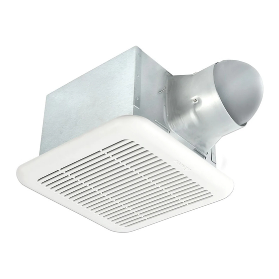
VENTILATION FAN / LED LIGHT /
READ AND SAVE THESE INSTRUCTIONS
Address: 46101 Fremont Boulevard, Fremont, CA 94538
US Toll Free Number: 1-888-979-9889
www.deltabreez.com
LED NIGHT LIGHT
MODELS SIG80-110 / SIG80-110D / SIG80-110H / SIG80-110MH /
SIG80-110LED/ SIG80-110DLED / SIG80-110HLED / SIG80-110MHLED
TABLE OF CONTENTS
2
3
4
5
6
7
11
12
13
14
15
15
16
Advertisement
Table of Contents

Related Manuals for Delta SIG80-110


Summary of Contents for Delta SIG80-110
-
Page 1: Table Of Contents
VENTILATION FAN / LED LIGHT / LED NIGHT LIGHT MODELS SIG80-110 / SIG80-110D / SIG80-110H / SIG80-110MH / SIG80-110LED/ SIG80-110DLED / SIG80-110HLED / SIG80-110MHLED TABLE OF CONTENTS Package Contents General Safety Information Preparation Wiring Diagrams Assembly Instructions - New Construction... -
Page 2: Package Contents
PACKAGE CONTENTS PART DESCRIPTION Fan Body Suspension bracket 6" to 4" adapter Grille HARDWARE CONTENTS (Images are to scale) Long Wood Screw ( 4 x 25mm) Short screw (#8-32x1/4”) SIG80-110 SIG80-110LED SIG80-110D SIG80-110DLED SIG80-110H SIG80-110HLED SIG80-110MH SIG80-110MHLED... -
Page 3: General Safety Information
GENERAL SAFETY INFORMATION READ AND SAVE THESE INSTRUCTIONS 7. If this unit is to be installed over a tub or shower, it must GENERAL SAFETY INFORMATION be marked as appropriate for the application and be connected to a GFCI (Ground Fault Circuit lnterrupter) – 1. -
Page 4: Preparation
Use a roof cap or wall cap that has a built-in damper to reduce backdrafts. External timer/dimmer switch can be used please contact Delta Breez customer service and consult with a licensed electrician for compatibility . For humidity sensing models only... -
Page 5: Wiring Diagrams
WIRING DIAGRAM Models: SIG80-110HLED, SIG80-110DLED Models: SIG80-110, SIG80-110MH JUNCTION BOX SWITCH BOX JUNCTION BOX SWITCH BOX BLACK WHITE POWER SWITCH WHITE LIGHT SWITCH GREEN YELLOW WHITE NIGHT-LIGHT SWITCH BLACK WHITE GROUND BLACK (bare) ON/OFF SWITCH SWITCH BOX WHITE POWER SWITCH... -
Page 6: Assembly Instructions - New Construction
ASSEMBLY INSTRUCTIONS NEW CONSTRUCTION – ATTACHING TO THE JOIST BEFORE INSTALLATION Turn off power source. Review all safety precautions. 1. If spacing between joists is 12 in. apart, use four Joist long wood screws (provided) to attach the fan body to ceiling joists, NO NEED FOR SUSPENSION BRACKETS. -
Page 7: Assembly Instructions - Existing Construction
ASSEMBLY INSTRUCTIONS 3. Remove the fan junction box cover . Using wire nuts (not supplied), connect house wires to fan wires as shown in the wiring diagram on page 5 . 14AWG is the smallest conductor that shall be used for branch-circuit wiring. - Page 8 ASSEMBLY INSTRUCTIONS 2. Measure the opening to ensure it is large enough to accommodate the new fan body (10 1/4 in. x 10 1/4 in.). 3. If this fan is not replacing an old fan, be sure to cut a 10 1/4 in. x 10 1/4 in. opening for the fan body Install from below, no need for suspension brackets (no attic access) 4.
- Page 9 ASSEMBLY INSTRUCTIONS 7. Remove the fan junction box cover . Using wire nuts (not supplied), connect house wires to fan wires as shown in the wiring diagram on page 5. 14AWG is the smallest conductor that shall be used for branch-circuit wiring. Reattach fan junction box cover 8.
- Page 10 ASSEMBLY INSTRUCTIONS Install from above with suspension brackets (attic accessible) *ONLY IF UNABLE TO ATTACH DIRECTLY TO JOIST(S) 1. For joist spacing 16 in.- 24 in., insert suspension bracket into the bracket cover on the duct Fan Body connector side and the back of the fan body Install the suspension brackets to the joists with long wood screw, and secure the suspension brackets to the fan body...
-
Page 11: Grille Installation
Slots SIG80-110HLED Celling Insert the LED light connector into the fan body. Spring LED light connector Grille Models: SIG80-110, SIG80-110D, SIG80-110H, Celling SIG80-110MH Spring Insert the motion sensor connector into the fan body (SIG80-110MH only). LED light connector Attach grille... -
Page 12: Operation
LED indicator will be blue. LED main light will be controlled LIGHT FAN/LIGHT by MODE switch ON/OFF. Single Speed Models: SIG80-110, SIG80-110LED If motion control switch to LIGHT position, when motion is • Turn the POWER switch on to operate at user- detected, the LED lighting will be on. -
Page 13: Care And Maintenance
CARE AND MAINTENANCE See safety information before proceeding. Routine maintenance should be done at least once a year. • Never use solvents, thinner or harsh chemicals when cleaning the fan. • Do not allow water to enter the motor. • Do not immerse metal parts in water. •... -
Page 14: Troubleshooting
TROUBLESHOOTING PROBLEM POSSIBLE CAUSE CORRECTIVE ACTION The fan is not turning on 1. Power off 1. Make sure power supply is on. 2. Faulty switch 2. Test or replace switch. 3. Faulty wire connection 3. Check wire in switch box. The fan seems louder 1. -
Page 15: Dimensions
DIMENSIONS Models: SIG80-110 / SIG80-110D Models: SIG80-110LED / SIG80-110DLED SIG80-110H / SIG80-110MH SIG80-110HLED / SIG80-110MHLED 13/16 7 7/8 13/16 7 7/8 (20.0) (200) (20.0) (200) 12 3/8 12 3/8 (314.0) (314.0) Unit: Inches(mm) 9 21/32 9 21/32 3 3/4 3 3/4 (245.4) -
Page 16: Warranty
6. To qualify for warranty service, you must notify Delta Electronics at the address or telephone number below. 7. Delta Electronics shall have no liability to the original owner-user with respect to any defect caused by abuse, misuse, neglect, improper transportation or storage, improper testing, improper installation, improper operation,...
Need help?
Do you have a question about the SIG80-110 and is the answer not in the manual?
Questions and answers