
Subscribe to Our Youtube Channel
Summary of Contents for SDMO MICS Telys
- Page 1 Instructions for use Telys level 1 1.06 F Réf. constructeur : Réf. GPAO : 33502012701 ind1...
- Page 2 S S A A F F E E T T Y Y S S Y Y M M B B O O L L S S C C O O N N T T E E N N T T S S ENGLISH 10/01...
- Page 3 SAFETY S S YMBOLS Caution : danger Caution, refer to the publications supplied with the Genset Protective clothing required. Caution : risk of electric shock Eye and hearings protection necessary Caution : toxic substances Periodic maintenance required Caution : pressuried fluids Check battery charge Caution : high temperature (risk of burning) Recommended Lifting point...
- Page 4 _____________________________________________________________________________________________________________________________________________________ 10/01...
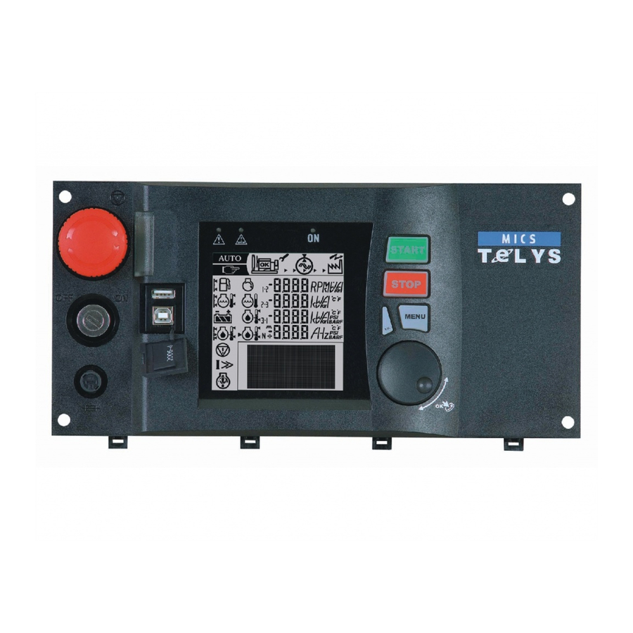
- Page 5 PRESENTATION K K e e y y E E N N G G L L I I S S H H C C o o n n t t r r o o l l u u n n i i t t Generating set programmable control- P P a a n n e e l l l l i i g g h h t t i i n n d d i i c c a a t t o o r r Lighting for wall mounted or free stan-...
- Page 6 USER MANUAL Level 1 CONTROL UNIT Due t t o o o ur o o n-g g oing r r esearch p p rogram a a nd t t he c c ontinual i i mprovements t t o o o ur p p roducts, w w e r r eserve t t he r r ight t t o m m ake a a ll c c hanges d d eemed n n ecessary w w ithout p p rior n n otice. All r r ights r r eserved a a s c c oncerns c c hanges t t o t t hese m m anuals.
- Page 7 Warning Changes to the front panel of the MICS Telys The MICS Telys front panel has been modified. Leaving aside the colour and design of the keys, the modifications are as follows: the "I" key has been changed to the "I/P" key (output measurements) the "F/ "...
-
Page 8: Foreword
- Display the status of the alarm and fault LEDs on the front panel of the display or retro- information concerning the position of the Normal/Backup switch. In addition, with software version 1.01B, the MICS Telys is automatically reset when the generating set is configured from a remote location. -
Page 9: Table Of Contents
Strating up the MICS TELYS ........ - Page 10 PRESENTATION A A ND T T ECHNICALS C C HARACTERISTICS 1. Oil pressure fault/shutdown (red LED on). 2. Water Tº fault/shutdown (red LED on). 3. Overcranking fault/shutdown (red LED on). 4. Overspeed fault/shutdown (red LED on). 5. Genset on load or ready to take the load (green LED on). 6.
- Page 11 1 1 - F F e e a a t t u u r r e e s s Display module (DM) Interface board available in 2 versions (CB, CB12) depending on customer optional equipment. Option 3 module, option 4 module and option 5 module (OPT 3 3 4) Block building system enabling multiple combinations.
- Page 12 5 5 - O O p p t t i i o o n n 3 3 , , 4 4 a a n n d d 5 5 m m o o d d u u l l e e s s ( ( O O P P T T 3 3 4 4 ) ) Modular case, dimensions : 160x90x58 Programming specific to each module (dip-switch) 8 allocated inputs and 10 programmable outputs on option 3 for remote volt free contacts...
- Page 13 1 1 6 6 - O O p p t t i i o o n n s s c c o o n n n n e e c c t t e e d d t t o o t t h h e e i i n n t t e e r r f f a a c c e e Option description CB12 external start-up command...
-
Page 14: Power Connection
1. F F OREWORD 1 1 . . 1 1 . . P P r r e e c c a a u u t t i i o o n n s s The control unit is connected to various AC voltage sources (alternator, mains, ...). While the generating set is idle, any work inside the control equipment is strictly forbidden as some parts of the electric and elec- tronic equipment stay live (mains voltage available). -
Page 15: Welcome Screens
The language selection screen is then displayed. The cursor flashes by default on "international". If no LANGUAGE SELECTION action is taken while the four squares are displayed in the small overlaid window, the MICS Telys is auto- V: Valid Esc: Exit matically positioned on the international language. -
Page 16: Overview " Screen
If neither V nor Esc is pressed, the " overview " screen appears after three minutes. There, the time and date will be those of the previous screen (before going automatically to the " overview " screen). Note : Not until the appearance of the " overview " screen will it be possible to start the generating set, however all engine protection shut- downs stay active (example: appearance of a fault). -
Page 17: Manu Mode
In this operating mode, any event appearance (alarm, fault, external command, ...) is signalled on screen. However, the generating set is stopped and automatic start-up is not possible. When the generating set is running and whatever the current mode (Auto, T T est, M M anu), press the Stop Ph./ph. -
Page 18: Sleep Mode
Press Test button again to confirm the mode, the associated red LED comes on continuously and the Fuel Lev(%) generating set then enters into an automatic start-up phase (see paragraph 17). When the red LED flashes (waiting for confirmation), the mode can be changed by selecting Stop E.Speed(RPM) mode or Auto mode. -
Page 19: Voltages
4. V V IEWING T T HE E E LECTRICAL V V ALUES 4 4 . . 1 1 . . V V o o l l t t a a g g e e s s You can view the various AC voltages by pressing the U/V button successively. Their values are expressed in true root mean square Volts. Depending on the client's needs (type of electrical installation), several screens are possible: 3 phase with neutral (3ph+N) 3 phase without neutral (3ph) -
Page 20: Currents
4 4 . . 2 2 . . C C u u r r r r e e n n t t s s To view the various AC currents, press the I button successively. The values are expressed in true root mean square Amps. Depending on the client's needs (type of electrical installation), several screens are possible: 3 phase with neutral (3ph+N) 3 phase without neutral (3ph) - Page 21 5. V V IEWING T T HE E E NGINE P P ARAMETERS To view the engine parameters, press the Engine button successively. Three different screens can be viewed. The values that can be displayed on these three screens are indications only. Screen 1 1 : : Press the Engine button to get the following screen.
- Page 22 All these LEDs are identified by an ISO symbol. The last two LEDs are flashing lights. The " general fault " LED flashes on appearance of any fault and the " general alarm " LED flashes on appearance of any alarm. Each blue coloured function button (Stop, M M anu, A A uto, T T est) is associated with a LED.
- Page 23 If a fault appears on screen 3, the message on the second line disappears from the screen, the message on the first line slides down to the second line and the fault message takes the first line. If a third fault appears on screen 4, the message on the second line disappears from the screen, the message on the first line slides down to the second line and the third fault message takes the first line.
- Page 24 - ATS toggle delay: Mains Stand-by and Stand-by Mains, and closure confirmation of the Mains and Stand-by contactors- Motorised C/B opening and closure - Engine cooling down time in Auto mode - Operating time in Test mode - Delayed shutdown on water temperature fault or overload/short-circuit fault - Appearance of commands ;...
- Page 25 In cases where the generating set is equipped with a differential protection (with communication) or with a constant insulation checking device (with communication), this menu is used to view the settings, fault current or insulation resistor. Note: Press the M button for three seconds to bring up that same GENERAL screen, followed by the first welcome screen (see paragraph 1.6), where the language, date and time can be changed at any time.
- Page 26 - High battery voltage - Overcranking (fail to start) - Overspeed - Charge alternator 12. " " S S TATUS " " M M ENU After validation using the V button, when the cursor flashes over the o sign next to Status, the STATUS screen appears as follows. This screen is used to view the list of the date and time stamped generating set status.
-
Page 27: Inputs " Menu
Main b b oard ( ( CB) Logical status display of the inputs on interface board CB, i.e. the eleven inputs described in Section " MAIN BOARD (CB) Technical characteristies ". Esc: Exit Note: the eleven inputs are also available on interface boards CB12. 123456789 10 11 * * * * * * * * * * * Input 1:... - Page 28 By setting parameter 903 to 1, the inputs of the option 5 module are displayed, programmed with John Deere OPTION 5 MODULE 6081HF engine. Esc: Exit Display of logical status of inputs of option 5 module. For the John Deere 6081HF engine., only inputs 1, 2 12345678 and 3 are used.
- Page 29 14. " " O O UTPUTS " " M M ENU After validation using the V button, when the cursor flashes over the o sign next to Outputs, the OUTPUTS screen appears as follows. 5 lines can be displayed at the same time on the screen. INPUTS The cursor flashes on the o sign of the first line.
- Page 30 Option 3 3 M M odule Logical status display of the ten outputs on option 3 module. OPTION 3 MODULE As these outputs can be programmed, the wording on each line varies according to the programming Esc: Exit performed. For that reason, the wording does not appear on the screen opposite. 123456789 10 * * * * * * * * * * Output 1:...
-
Page 31: Differential Protection
Viewing the outputs on an option not available (see note) or on an option module not available (factory configuration) on the cabled sys- tem will result in the following superimposed message to be displayed. Example: a system is configured with interface board CB12 and Option 3 module. Press V, when the OUTPUTS cursor is next to Option 4 4 M M odule, to display the superimposed message opposite. - Page 32 - The delay setting can be displayed between 0 and 10 seconds, with: - a display in milliseconds between 0 and 100ms - a display in seconds above 100ms - The fault current percentage displayed varies according to the relay initial setting. Example: relay set to 300mA, fault current=150mA, the screen display will be of 50%.
- Page 33 1 1 7 7 . . 4 4 . . S S t t a a r r t t e e r r c c o o n n t t r r o o l l On appearance of the external command (immediate or associated with the end of the power failure delay) or at the end of the engine preglow period, the starter is cranked for an adjustable time (factory programmed).
-
Page 34: Generating Set Operation
In Auto mode, when one of the three start-up conditions changes (see paragraph 2.3), the Stand-by contactor opens automatically, the Mains contac- tor closes after the S¢M toggle delay and the engine enters into a cooling down phase. At the end of the cooling down period, the engine stops and the generating set is on stand-by again. -
Page 35: Ats Operation
1 1 - I I n n t t r r o o d d u u c c t t i i o o n n Software version 1.05E used with interface boards CB and CB12 enable you to use the MICS Telys in a language which is different from the four stan- dard languages already implemented. - Page 36 3 3 - M M o o d d i i f f y y i i n n g g d d i i s s p p l l a a y y w w i i t t h h i i n n t t e e r r n n a a t t i i o o n n a a l l l l a a n n g g u u a a g g e e When the international language is selected on power up or during use: - The time and date are no longer displayed on the screen.
- Page 37 5 5 - D D i i s s p p l l a a y y o o f f m m e e c c h h a a n n i i c c a a l l v v a a l l u u e e s s By pressing the Engine button successively, the following is displayed: oil pressure, water temperature, oil temperature, battery voltage, engine speed and fuel remaining in daily tank.
- Page 38 Return of system voltage (symbol 10) Return of the system voltage (or mains voltage) is represented on the screen by a transformer. The mains return time delay (para- meter 104 of Timing menu) is displayed next to this symbol and decrements automatically from the adjustment setting to 0. Example of screen showing system voltage is again available.
- Page 39 Fault takes priority over alarm Faults are reset in order of appearance For more details, refer to paragraph 8. All the alarms and faults which can appear on the MICS Telys screen are listed in the table below.a. Wording Alarm...
- Page 40 Wording Alarm Fault Generated on MTU engine oil pressure impossible 48-1 module 5 MTU engine HV water temperature impossible 49-1 module 5 MTU engine overspeed impossible 50-1 module 5 MTU engine general fault impossible 51-1 module 5 MTU engine gener al alarm 52-0 impossible module 5...
Need help?
Do you have a question about the MICS Telys and is the answer not in the manual?
Questions and answers
How to set Operation setting auto manual if it is hidden in display
To access the operation setting for auto/manual on an SDMO Telys when it is hidden in the display:
1. Use the four blue buttons on the display module to navigate between modes.
2. If the operation setting is not visible, press the buttons successively to modify the screen until the desired mode (Stop, Automatic, etc.) appears.
3. Once the mode is visible, use the V button to validate your selection.
This allows you to switch between Stop and Automatic modes as needed.
This answer is automatically generated