Sign In
Upload
Download
Table of Contents
Contents
Add to my manuals
Delete from my manuals
Share
URL of this page:
HTML Link:
Bookmark this page
Add
Manual will be automatically added to "My Manuals"
Print this page
×
Bookmark added
×
Added to my manuals
Manuals
Brands
ELTEX Manuals
Gateway
SMG-4
Operation manual
ELTEX SMG-4 Operation Manual
Digital
Hide thumbs
1
2
3
4
Table Of Contents
5
6
7
8
9
10
11
12
13
14
15
16
17
18
19
20
21
22
23
24
25
26
27
28
29
30
31
32
33
34
35
36
37
38
39
40
41
42
43
44
45
46
47
48
49
50
51
52
53
54
55
56
57
58
59
60
61
62
63
64
65
66
67
68
69
70
71
72
73
74
75
76
77
78
79
80
81
82
83
84
85
86
87
88
89
90
91
92
93
94
95
96
97
98
99
100
101
102
103
104
105
106
107
108
109
110
111
112
113
114
115
116
117
118
119
120
121
122
123
124
125
126
127
128
129
130
131
132
133
134
135
136
137
138
139
140
141
142
143
144
145
146
147
148
149
150
151
152
153
154
155
156
157
158
159
160
161
162
163
164
165
166
167
168
169
170
171
172
173
174
175
176
177
178
179
180
181
182
183
184
185
186
187
188
189
190
191
192
193
194
195
196
197
198
page
of
198
Go
/
198
Contents
Table of Contents
Bookmarks
Table of Contents
Firmware Version
Explanation of the Symbols Used
Target Audience
Table of Contents
Introduction
1 Device Description
Purpose
Typical Applications
Interface for TDM and Voip Network Signalling and Media Streams
Device Design and Operating Principle
Main Specifications
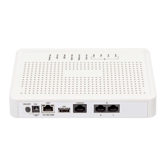
Design
LED Indication
The F Function Button
Delivery Package
Safety Instructions
General Guidelines
Electrical Safety Requirements
2 Smg Installation
Startup Procedure
Opening the Casing
RTC Battery Replacement
3 General Guidelines for Gateway Operation
4 Device Configuration
SMG Configuration Via Web Interface
System Parameters
Monitoring
Synchronisation Sources
Cdr
E1 Streams
Dial Plan
Routing
Internal Resources
Network Services
User Configuration
Security
Network Utilities
RADIUS Configuration
Tracing
Working with Objects and the Objects Menu
Saving Configuration and the Service Menu
Time and Date Settings
Firmware Upgrade Via Web Interface
Licence Renewal
Help Menu
Password Configuration for Web Configurator Access
View Factory Settings and System Information
Configurator Exit
Command Line, List of Supported Commands and Keys
System of Commands for SMG Gateway Operation in the Debug Mode
Tracing Commands Available through the Debug Port
SMG Configuration Via Telnet, SSH, or RS-232
List of CLI Commands
Changing Device Access Password Via CLI
Statistics Mode
Management Mode
General Device Configuration Mode
СDR Configuration Mode
Access Categories Configuration Mode
E1 Stream Configuration Mode
Fail2Ban Configuration Mode
Firewall Configuration Mode
SS7 Line Group Configuration Mode
Modifier Table Configuration Mode
Network Parameter Configuration Mode
Numbering Schedule Configuration Mode
Timer Configuration Mode
RADIUS Configuration Mode
Static Route Configuration Mode
SIP/SIP-T General Configuration Mode
SIP/SIP-T Interface Configuration Mode
Category Modification Configuration Mode
Timer Configuration Mode
Sync Configuration Mode
Syslog Configuration Mode
Trunk Group and Trunk Direction Configuration Mode
5 Appendix A. Cable Contact Pin Assignment
6 Appendix B. Alternative Method of Device Firmware Update
7 Appendix C. Examples of Modifier Operation and Device Configuration Via Cli
8 Appendix D. Correlation between Routing, Subscribers, and Signal Link Parameters
9 Appendix E. Guidelines for Smg Operation in a Public Network
10 Appendix F. Device Interaction with Monitoring Systems
11 Appendix G: Configuration of E1 Channels Transit through a Semipermanent Connection
12 Technical Support
13 Acceptance Certificate and Warranty
Advertisement
Quick Links
1
The F Function Button
2
Smg Configuration Via Web Interface
Download this manual
Digital gateway
SMG-4, SMG-2
Operation manual, version 2.4 (15/06/2017)
Firmware version: 3.1.6.1189
Table of
Contents
Previous
Page
Next
Page
1
2
3
4
5
Advertisement
Table of Contents
Need help?
Do you have a question about the SMG-4 and is the answer not in the manual?
Ask a question
Questions and answers
Related Manuals for ELTEX SMG-4
Gateway ELTEX SMG-2 Operation Manual
Digital (198 pages)
Gateway ELTEX SMG-1016M Operation Manual
Digital gateway (441 pages)
Gateway ELTEX SMG-2016 Operation Manual
Digital gateway (441 pages)
Gateway ELTEX TAU-4.IP Operation Manual
Voip gateway (190 pages)
Gateway ELTEX TAU-8.IP User Manual
Ip-telephony customer gateway (102 pages)
Gateway ELTEX TAU-4M.IP Operation Manual
(126 pages)
Gateway ELTEX TAU-8N.IP User Manual
(107 pages)
This manual is also suitable for:
Smg-2
Table of Contents
Print
Rename the bookmark
Delete bookmark?
Delete from my manuals?
Login
Sign In
OR
Sign in with Facebook
Sign in with Google
Upload manual
Upload from disk
Upload from URL


Need help?
Do you have a question about the SMG-4 and is the answer not in the manual?
Questions and answers