
Summary of Contents for Cleveland Steel Tool 55 Ton
- Page 1 55 Ton Ironworker Manual Serial #__________________________ 800-446-4402 www.clevelandsteeltool.com 474 E. 105th St. • Cleveland, OH 44108...
-
Page 3: Table Of Contents
Table of Contents Company Profile, Warranty Operator and Supervisor Information Requirements Signal Panel Information Installation Machine Front View Machine Back View Machine Side Views Maintenance Precautions and Schedule Operations Diagram Control Panel Electric Stroke Control Flat Bar Shear Station Flat Bar Shear Station Maintenance Angle Shear Station Angle Shear Station Maintenance Optional Tooling - Auto Cut... - Page 4 55 Ton Ironworker Technical Specifications Rated capacity 55 Ton **Rated at 65,000 psi tensile strength Number of work stations Throat depth " Maximum capacity " dia. thru 5/8" plate Largest standard punch " punch Open height " Closed height "...
-
Page 5: Company Profile, Warranty
Company Profile The Cleveland Steel Tool Company offers a full line of high quality, low maintenance hydraulic ironworking machines, associated tooling and accessories that are used in the steel fabrication industry. With proper operation, care, and maintenance, your Cleveland Steel Tool Ironworker... -
Page 6: Operator And Supervisor Information
Do not resell, relocate or export to a destination other than to the original point of sale. Cleveland Steel Tool has designed this machine to meet the standards of the original receiving country and is not liable for meeting any governing body or performance standards beyond those of the original receiving country. -
Page 7: Requirements
Environmental Requirements Environmental Requirements Cleveland Steel The work station environment for your Locate your Cleveland Steel Tool Ironworker directly Tool Ironworker must meet the following minimum adjacent to your power supply. Confirm that power supply requirements: is not connected in series with other machinery. Provide dedicated electrical socket and circuit breaker for each •... - Page 8 Danger Panel Warning Panel Electrical Hazard Shear/Crush Hazard High voltages present inside the enclosure of Moving parts can cut and crush. Keep hands this product. ONLY qualified, authorized, mainte- clear while operating. Lockout power before nance, service or Certified Electricians should gain servicing.
- Page 9 Regardless of the contents of the Conformité Européenne machinery manual, Cleveland Steel Tool will not be Conformity with all legal requirements pertaining held liable for accidents caused by lack of training.
- Page 10 With all stations clear of tools, tooling or debris, power up the Ironworker by depressing the green button on the Your Cleveland Steel Tool Ironworker includes surface and starter box. With the power on, your machine will return to remotely mounted electrical cabling and hydraulic lines. Ex- a neutral position.
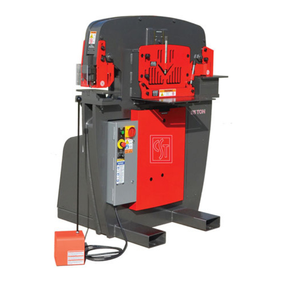
- Page 11 Signal Word Panel • Machine Front KEEP OUT Hazardous voltage inside. Lockout power before servicing.
- Page 12 Signal Word Panel • Machine Back FLUID INJECTION HAZARD Hydraulic fluid is under pressure. Hydraulic fluid powers moving parts. Keep guards in place.
- Page 13 Signal Word Panel Machine Right Machine Left SHEAR/ CRUSH HAZARD Moving parts can cut and crush. Keep guards in place.
-
Page 14: Maintenance Precautions
1,000 hours of use. External oil filters are available through vibration that may loosen hardware and fasteners over time. Cleveland Steel Tool. When working on the hydraulic power, Inspect fasteners and fittings and tighten where loose. use plugs to cap hose ends during maintenance procedures Slipping, Tripping and Falling to minimize fluid loss. -
Page 15: Operations Diagram
Operations Diagram Grease Daily Open Tooling Station Punch Station Electric Stroke Control Angle Shear Flat Bar Shear Grease Daily 5 Locations Control Panel Front Cylinder Guard Foot Pedal Visit our website to view our Ironworkers in action. https://www.clevelandsteeltool.com/catalog-and-literature/videos... -
Page 16: Control Panel
Reverse operation following service to resume Ironworking. Cleveland Steel Tool Ironworkers feature a centrally located, integrated Control Panel. Hazardous voltage is present within the control panel. The panel should only be opened and serviced by authorized personnel. -
Page 17: Electric Stroke Control
Electric Stroke Control Electric Stroke Control Operation Set upstroke for rapid cycling of your punching, shearing and notching stations. 1. Power machine on and use the jog function of your electric foot pedal to bring tooling down to rest just above the material being worked. -
Page 18: Flat Bar Shear Station
Flat Bar Shear Station Bar Shear Operation 1. Clear bar shear station of any tools or debris prior to powering the machine on. 2. Turn machine on. The shear blades will be in their neutral position. Place bar stock on the feed table and push the material under the material hold-down. - Page 19 Maintenance - Flat Bar Shear With bolts exposed, turn machine off and disconnect from power source. 4. Remove blade bolts and remove blade from the blade pocket. 5. With blade removed, clean blade pocket of any dirt or debris. 6. Your shear blades have four cutting surfaces that can be used prior to full replacement of the part.
-
Page 20: Angle Shear Station
Angle Shearing Station. The Angle 2. Turn machine on. The shear blades will be in their Shearing Station on the Cleveland Steel Tool Ironworker neutral position. Place angle iron into the material allows for straight cutting applications. An oversized material... - Page 21 Maintenance - Angle Shear Station 7. Tighten the movable blade back into the blade pocket. 8. Replace the drop-off guard to the rear of the Ironworker frame. 9. Return the machine to power and turn on to automatically return the moving center to its neutral position. 10.
-
Page 22: Optional Tooling - Auto Cut
Optional Tooling - Auto Cut Safe Operation Observe the following guidelines when operating the Auto- Cut Tool: • Never exceed the capacities of the machine or tooling as described in the Ironworker specifications or listed at the tooling station. • Check shear blade clearance at every tooling change or extended shear operation. -
Page 23: Optional Accessory Light
Magnet Safety Warning! 4. Children should not be allowed to handle neodymium Disclaimer: Cleveland Steel Tool neither assumes nor accepts any liability for magnets as they can be dangerous. Small magnets pose a damages resulting from the handling or use of magnets. With your purchase,... -
Page 24: Punch Station
Setup • Check punch and die alignment after every tooling Your Cleveland Steel Tool Ironworker has been shipped change or extended punch operation. with a punch and die installed within the punch station. Punches and dies are wearing parts and will need to •... -
Page 25: Punch Operation
Punch Operation Round Holes Clear the punch station of any tools or debris prior to Punch Dia. x Material Thickness x 80 = Tons of pressure required powering the machine on. Example: How many tons of force do I need to punch a 1. - Page 26 • Follow manufacturer punch and die clearance and tonnage recommendations as shown in Figure 2, page Cleveland Steel Tool Ironworkers allow for Oversize 228 Punch • Never exceed the capacities of the machine or tooling and 419 Die tooling to be installed in either the punch station as described in the specifications or listed at the tooling or the open station.
- Page 27 Guarding removed for clarity Safe Operation Cleveland Steel Tool Ironworkers allow for Oversize 241 Punch Observe the following guidelines when operating the 241 and 28XX Die tooling to be installed in either the punch station Punch Station.
-
Page 28: Punch Station Maintenance
Punch Station - Maintenance Guarding removed for clarity Your Cleveland Steel Tool Ironworker has been shipped with a punch and die installed within the punch station. When worn or chipped, the punch and die must be replaced. Observe the following procedure when maintaining the ironworker punch station. -
Page 29: Punch And Die Styles
241 Tip Holder 2-1/8 2-11/16 2-3/8 1-1/4 241 Punch Tip Available up to 4-1/2" DIES 4-3/4 2-3/8 1-13/16 1-5/32 1-1/4 1-1/8 28XX Cleveland Steel Tool Ironworkers use 1/4" x 1/8" Keyways and Whistle Spots for alignment of shaped punches and dies. -
Page 30: Optional - Angle Notcher
Optional Tooling - Angle Notcher 3. Check for push block and top blade alignment by power- ing on the machine and slowly inching down the push block to meet the top blade with the foot pedal. Power the machine off. In the event that the push block and top blade are not aligned, simply loosen the bolts under the table allowing the table to be moved to center the push block centerline... - Page 31 Maintenance - Angle Notcher Remove and replace stationary blades: The Angle Notcher base table includes two blades secured within the table housing. Remove the four 1/2" socket head cap screws that secure the blades into the blade supports of the base table housing. 2.
- Page 32 If the punch stops before the material has been formed to a 90 degree angle, a small steel shim The 55 Ton Cleveland Steel Tool Ironworker can accommo- must be placed between the die and support table.
- Page 33 Maintenance - Press Brake Tooling Remove and replace stationary Four-Way Die: 1. Remove four 1/2" bolts, nuts and washers from the die support brackets. 2. Remove support brackets. 3. Remove old die assembly. 4. Place new die assembly on the Ironworker support table. 5.
-
Page 34: Optional Coper Notcher
Notching Station. The optional described in the Ironworker specifications or listed at the tool- Coper Notcher tooling for a Cleveland Steel Tool Ironworker al- ing station. lows for shaped, straight or angled notch cutting applications. - Page 35 Maintenance - Coper Notcher 4. Remove the six 3/8" socket head cap screws that secure the blades into the base table housing. 5. Clean the blade pockets of any dirt or debris. 6. The bottom shear blades have multiple cutting surfaces. Either rotate/flip the existing blade set to the new cutting surfaces or install new cutting blades into the blade pock- ets.
-
Page 36: Optional Pipe Notcher
Optional Tooling - Pipe Notcher 2. Loosely secure the table from the underside of the base with four 1/2" bolts and washers (provided). 3. Check for push block and top die alignment by powering on the machine and slowly inching down the push block to meet the top die with the foot pedal. - Page 37 Maintenance - Pipe Notcher 4. Re-install the push block to the moving center with the two 1/2” socket head cap screws provided. Remove and replace stationary blade: The Pipe Notcher base table includes one blade secured within the table housing. Remove the two 1/2" socket head cap screws and washers that secure the blade into the base table housing.
- Page 38 Optional Tooling - Rod Shear/Multi-Shear Install the assembly: 1. Remove all tooling and guarding from the appropriate punch station or open station. 2. Place the Rod Shear or Multi-Shear assembly on the Iron- worker support table with the push block in line with the moving center.
- Page 39 Maintenance - Rod Shear/Multi-Shear 3. Install new cutting blades into the blade pocket. Re- install the guarding and the six 1/2" socket head cap screws and spacers provided and tighten. 4. Check for moving and stationary blade alignment by powering up the machine and slowly jog the center down.
- Page 40 The Hydraulic Accessory Package is a option 6. Attach the accessory tool control OUT / IN, male M12 that is ready to power any Cleveland Steel Tool Hydraulic control cable to the M12 female accessory control port. Accessory Tool. The Hydraulic Accessory Package includes 7.
-
Page 41: Exploded View
55 Ton Exploded View... -
Page 42: Parts List
55 Ton Parts List... -
Page 43: Troubleshooting
Your Cleveland Steel Tool Ironworker is designed for years of trouble-free use. In the event of operational problems, refer to the following troubleshooting strategies prior to contacting Cleveland Steel Tool. Turn off power to machine by depressing the red stop / off button or lockout upstream power at the main electrical panel before any trouble shooting activity. - Page 44 www.clevelandsteeltool.com 474 E. 105th St. • Cleveland, OH 44108 800-446-4402...
Need help?
Do you have a question about the 55 Ton and is the answer not in the manual?
Questions and answers