Table of Contents
Advertisement
Quick Links
Advertisement
Table of Contents

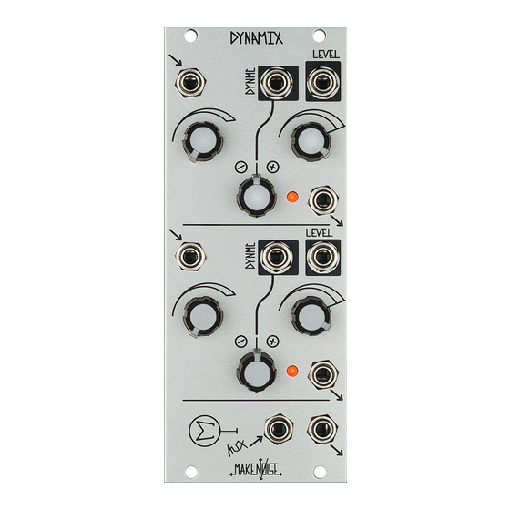
Summary of Contents for Make Noise DynaMix
- Page 1 v 1.0...
-
Page 2: Table Of Contents
Table of Contents: ----------------------------------------------------2 Limited Warranty: ----------------------------------------------------3 Installation: ------------------------------------------------------------4 Overview:------------------------------------------------5 Panel Controls: -----------------------------------------------6 Getting Started: -------------------------------------------------7 Dynamics Management: -------------------------------------------------8 Tips and Tricks: ------------------------------------------------9 Patch Ideas: ------------------------------------------------10... -
Page 3: Limited Warranty
Make Noise to be the fault of the user are not covered by this warranty, and normal service rates will apply. During the warranty period, any defective products will be repaired or replaced, at the option of Make Noise, on a return-to-Make Noise basis with the customer paying the transit cost to Make Noise. -
Page 4: Installation
Do not touch any electrical terminals when attaching any Eurorack bus board cable. The Make Noise DynaMix is an electronic music module requiring 55 mA of +12VDC and 45 mA of -12VDC regulated voltages and a properly formatted distribution receptacle to operate. It must be properly installed into a Eurorack format modular synthesizer system case. -
Page 5: Overview
Coast synthesis circuit: the ADSR: a 4-stage Envelope generator we call CONTOUR. As a VCA, the DynaMix has a fast Attack and Decay response, meaning that it turns on and o quickly, allowing for highly-articulated transients. As a VCF, it is a mild, non-resonant Low Pass circuit, acting to gently reveal (or hide) the sharper edges of a sound. -
Page 6: Panel Controls
14. Channel 2 Level Combo Pot: Unipolar attenuator for Control Signal Input. With nothing patched to the Level CV Input, operates as a manual control for the Level parameter. 15. Channel 2 Signal Output: Output of the signal applied to the Channel 2 input, as processed by the DynaMix. 10Vpp (depending upon settings and source material). -
Page 7: Getting Started
One way to listen to the e ect of the DynaMix is to patch a harmonically-rich audio signal, such as a Frequency-Modulated VCO to the Signal Input. Next, set the Level Panel Control to Full counter clockwise. You should hear no sound. Slowly sweep the Level Panel Control to Full Clockwise. -
Page 8: Dynamics Management
Processing Control Voltage w/ Audio Signals and More The Signal Input is Direct Coupled so it is possible to use the Dynamix to process Control Voltages as well. There is both gain and attenuation available at the Signal Input which might be helpful when you need to translate between di erent systems or modules. -
Page 9: Tips And Tricks
-The Signal Input starts to overload when the signal at the input is 10V and the associated attenuator is set beyond about 3:00. -To get more dramatic overload, run two channels of the DynaMix in series with the Signal Input set to maximum on both channels and the Level parameter set to maximum on the rst channel. -
Page 10: Patch Ideas
Sine wave to its Linear FM Input or using the DPO’s FM Bus and patching the resulting waveform to DynaMix’s Input. Set the associated attenuator to 4:00. Patch an Exponentially-shaped Envelope CV with a fast Rise or Onset and a slower Fall or Decay and no Sustain to the Level CV Input.
Need help?
Do you have a question about the DynaMix and is the answer not in the manual?
Questions and answers