Blu Life One Service Manual
Hide thumbs
Also See for Life One:
- User manual (20 pages) ,
- User manual (21 pages) ,
- Service manual (39 pages)

Related Manuals for Blu Life One


Summary of Contents for Blu Life One
- Page 1 BLU Life One Service Manual...
- Page 2 CAUTIONS Please refer to the phone’s user’s guide for instructions relating to operation, care, and maintenance, which include important safety information. Servicing and alignment must be undertaken by qualified personnel only. Ensure all work is carried out at an anti-static workstation and that an anti-static wrist strap is worn. Use only approved components as specified in the parts list.
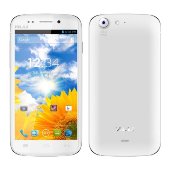
- Page 3 CHAPTER 1 INTRODUCTION S9111 Main function *5.0" HD 1280*720 Android 4.2 * CPU MT 6589 ) , *MT 6589 (1.2GHz 1.2G Quad core 16GB eMMC+8Gb Dual SIM *Google Pinyin IME, Android keyboard, Touchpal *LCD IPS 5.0` HD 1280*720 *Camera: front: 5FFMega /rear: 13 AF Mega auto focus with flash *WIFI, BT , FM , SENSOR,GPS, *Multimedia player...
- Page 4 Chapter 2 Exploded View 1.TP 6.LCD 7.Side key 9.Power key 11.Front host Silica gel 20.Front camera 21.Reciver 27.Main camera 29.SIM/TF FPC 33.Back cover 38.AGPS Antenna 39. Battery cover 40.Main Antenna 42.Battery cover 47.Speaker 48.Vibrator 50.RF coaxial line CHAPTER 3、SERVICE TOOLS...
- Page 5 Hot air gun Iron Voltage regulator Multimeter Solder wire, soldering paste Tweezers Driver upDownlo ad cable Wrist groun ding strap Pick Antistatic gloves Computer and software download cable Metal tweezers, Screw driver etc...
- Page 6 CHAPTER 4 DISASSEMBLY AND ASSEMBLY DISASSEMBLY Remove battery cover……………………………... 1 Take down the 7 screws………………………..…2 Open the back cover Take out the Side key FPC…………………………4 Open the LCD FPC connector……………………..5 Open the TP FPC connector….…………….……... 6 Take out the power key FPC..………………...……7 Open the RF line …………..……………………..8...
- Page 7 Remove the three in one connector………………….9 Remove the FPC……………...……………………10 Open the camera by tweezers…………………...…11 Remove the camera………………………………..12 Remove the PCBA………………..……………….13 Remove the RF line……..…………………………14...
- Page 8 Open the FPC connector……………...……………15 Remove the vibrator…………….…………………16 Remove the small PCBA…………...………...……17 Heat the TP around use hot air gun (200 degree)…18 Remove the TP with sucker………………………..19 Remove the TP ………………………………….20...
- Page 9 Paste the protect for the TP inside……………..…..21 Paste LCD protect film………….…………………22 Take out the LCD with press………………………23 Remove the LCD…………………………………..24 Finished。 。 。 。 。 。 。...
- Page 10 ASSEMBLY Button the LCD by hand……...……………………2 Install the LCD……………………..…..………..…1 Remove LCD protect film………………………….4 Remove TP protect film……………………………3 Button the TP by hand…………………………..6 Install the TP…………..…………………………...5...
- Page 11 Install the small PCB………...…………………..…7 Install the FPC……………………...………………8 Install the vibrator ………………………………... 9 Install the power key………………...……………10 Install the silica gel cover for proximity sensor…12 Install the side key………...………………………11...
- Page 12 Install the PCB………………………..……..……13 Install the LCD FPC……….……...………………14 Install the Side key FPC ………………………….15 Install the TP FPC connector…………...…………16 Install the FPC…………...……..…………………18 Install the power key FPC…...……………………17...
- Page 13 Install the three in one connector…..…………..…19 Install the RF coaxial line……………...…………20 Install the camera…………………………………21 Install the back cover…………..…………………22 Install the battery cover………………………...…24 Fasten the 7 screws.……………………….………23 Finished………...
- Page 14 CHAPTER5. SYSTEM BLOCK DIAGRAM 5.1、PCBA A-Side J1102 Front 1201 J1002 TP camera Connector J1101 Main U901 Camera Four in one IC MT6628 U803\U804 J1402 WCDMA PA Three in one U708 RF IC Connector MT6167 J1001 LCD U801 2G PA Connector SKY775XX J1401 J501...
- Page 15 Side A layout Side B layout...
- Page 16 CHAPTER 6、CIRCUIT INSTRUCTION CHAPTER 7、UNIT CIRCUIT PRINCIPLE INTRODUCTION...
- Page 17 MT6589 INTRODUCTION System Overview MT6589 is a highly integrated baseband platform incorporating both modem and application processing subsystems to Enable 3G smart phone applications. The chip integrates a Quad-core ARM Cortex-A7 MPCore operating up to 1.2GHz, an ARM Cortex-R4 MCU and a powerful multi-standard video accelerator. The MT6589 interfaces to NANA flash memory, 32-bit mobile DDR or LPDDR2 for optimal performance and also supports booting from SLC NAND or EMMC to minimize the overall BOM cost.
- Page 18 Circuit for sensor interrupt request USB data transmission USB date communication Multi-media data transmission Porwer data transmission Charging data transmission SIM data transmission card data transmission Controller LCD data transmission...
- Page 19 Data transmission mailing address...
- Page 20 Four in one MT6628 MT6628 is a 4-in-1 wireless communication device which includes . WLAN . Bluetooth . GPS . FM Transmitter and receiver With four advanced radio technologies integrated into a single chip, MT6628 provides the best and most convenient Connectivity functions.
- Page 21 Power management IC MT6320 General Descriptions MT632O is a fully integrated PMIC target for smart phone power provider. See Figure 3-1 the block diagram for the whole picture of MT6320 PMIC 4.5 WCDMA PA IC...
- Page 22 Description The SKY7775XX Power Amplifier Module (PAM) is a fully matched 10-pad surface mount module developed for Wideband Code Division Multiple Access (WCDMA) applications, This small and efficient module packs full 1920-1980 MHz bandwidth coverage into a single compact package. Because of high efficiencies stained throughout the entire power range, the SKY7776X delivers unsurpassed talk-time advantages.
- Page 23 SKY7775XX POWER AMPLIFIER MODULE FOR CDMA/WCDMA/HSDPA/HSUPA/HSPA+/LTE- DAND...
- Page 24 Chapter 8TROUBLESHOOTING Cannot power on-current swing instability Make the phone connect the power supply and find the current swing at 50-100mA Upgrade the software Check and replace the I/O connector Check the power manage supply output: VCCRE 1.8V VDD 2.8V Replace or AVDD 2.8V reweld...
- Page 25 Make the phone connect the power Make the phone connect the power supply and find low or no current supply and find low or no current Check Check battery battery Clean,reweld connector and power key connector and power key or replace it Upgrade the software Check and replace I/O connector...
- Page 26 Make the phone connect the power supply and then press power key find large current make the phone heat Check if the phone leakage (current 0mA is normal) Use the Check and touch replace RF method to PA, Audio Check if the capacitance, varistor, LDO tube leakage check and PA, PM IC...
- Page 27 Phone dead Upgrade the software can Upgrade the settle the defect issue? Software. Check battery connector Clean or replace the battery and battery touch point if or battery connector. is dropped or dirty? Check the keypad if stuck or Check and reinstall the keypad touch panel do not work to or replace the touch panel.
- Page 28 No display or display abnormality No display or display abnormality after power on Check LCD if damage Change LCD or liquid flow out Check LCD Clean/re-solder connector is OK or connector Change LCD FPC Problem solve Upgrade software Check if 1 PIN of J901 have signal or not, check 38 digit cable status...
- Page 29 TP can’t work TP can’t work Do calibration first Problem solve Upgrade software Problem solve Re-solder Check the connect status or reassemble between TP and PCB Problem solve Change TP Check voltage of PCBA FPC connector is OK or not Check the working status of Change inductance R803\R805\R808 is Ok or not...
- Page 30 Insert SIM Repair Process Insert SIM Clean or replace Check if all the SIM connector. SIM pins are clean Resolved If SIM card Replace SIM card is available CPU MT6589 Connect Power supply may be defective to check the current MT6589 may be defective Resolder or replace...
- Page 31 N0/weak signal trouble shooing No or weak signal Inspect the antenna and Replace the defective antenna connector to see components. if there’s any distortion Put a false antenna at RF PA Replace RF PA IC. IC to see if there’s any signal Make a false antenna at Saw filter is damaged, Z602, check if there’s...
- Page 32 No/Low sound from Speaker No sound or noise Remove the speaker and Press power on and side button to measure with multimeter to check if there’s the ring is normal see if there’s any sound. Set the phone as The phone is in Replace speaker.
- Page 33 Receiver low voice or no voice Receiver is low. Set the phone as Check if J1103 handsfree mode is damaged. Resolder clean J1103 Check if the receiver Replace the is broken or damaged receiver. Test if there’s sound from Replace receiver receiver with multimeter Measure the signal with oscillograph...
- Page 34 No/Low sound from MIC No/Low sound from MIC Check if there’s Install the MIC cover MIC cover Press power on and side button to test mode and activate echo loop, measure Replace MIC MIC MK1001 voltage is 1.5V、0.7V ReplaceB1108 or B1109 Check if inductor B1108、...
- Page 35 Does not charge – remind error charge Remind error during charge Remind: “fault connection” “battery overheat” Change battery Re-flash SW Check battery connector testing Pin, if the bias resis and vatge be normal. Check resistor R1313\R1314 be normal Replace Check charge protective tube re-solder be normal.
- Page 36 Does not charge – no charge No charge Change battery Re-flash SW Check charger and cable without problem, or change good one Check if I/O connector works normal Connect the charger without battery put in, check if the voltage of positive pole is around 3.6V. Replace Check charge protective tube be re-solder...
- Page 37 Does not charge – does not recognize charging If recognize “charger connected” There is no symbol shows charging Re-solder or replace Power on and connect charger, check if ADC is around 0.40A connector Change battery Re-flash SW Connect the charger without battery put in, check if the voltage of positive pole is around 3.6V.
- Page 38 Stand-by short time Stand-by short time Change battery Re-flash SW Connect the phone with Voltage regulator, the current should be zero Power on the phone, check the if working current be By touch to Check and find the replace normal(no exceed 600mA) component RF- PA, getting hot,...
- Page 39 Can’t read T-Flash card Can’t read T-Flash card Check if T-Flash Replaced the slot appearance T-Flash slot was ok? Measure if Re-solder T-Flash slot pin 4 T-flash slot VMC was 2.8V. Check if the voltage of T-Flash Measure if there is pin pin3/pin5/pin7 to the ground was around short for the T-flash 0.7V with multimeter diode column...
- Page 40 WIFI、BT、FM 、GPS defect repair flow chart WIFI can’t open, Can’t work normal Software update and check Software update the function is OK or not Check U901 L12 pin have 3.7V +B supply voltage or Check C801 have VBATT Replace U901 V supply voltage or not Check U903 3pin have Replace U903...
- Page 41 Chapter 9 Firmware Upgrading Guide Firmware Upgrading 1. Install USB driver The maximum downloading speed can be up to 921600bit/s when using USB-Serial cable. The driver needs to be installed before using the USB cable. 1> computer eject hardware installation instruction and choose following item and then click’’next step’’ Choose next step 2>...
- Page 42 4> click’’ finished’’ as below. Click here...
- Page 43 2>. Software upgrade 1> Open software upgrading platform’’SP_Flash_Tool_exe_v2.1129.00 2> Choose ’’USB mode’’ 3>choose’’ Back up restore’’===>’’No action’’ 4> Click ‘Scatter-loading’’ to choose file’’MT6513_Android_scatter.txt’’...
- Page 44 Choose this 5> Cancel the two items as below ’’PRELOADER’’ and ‘’DSP-BL’’ and then click’’ download’’, then install USB cable and battery to the unit, press ’’Home’’ button, it begin to show the yellow progress index bar until it finished as below. Cancel items 6>...
- Page 45 7> Finished. Description: can’t power on (also upgrade software fail) Root cause: red scroll 100% run completely when upgrade software, the detail as figure 1, also it prove power...
- Page 46 supply, clock is normal and defective typical issue is focus on CPU or FLASH poor soldering or damage, and maybe software do not fit for hardware. Corrective action: check software fit for hardware whether or not, resolding CPU and FLASH or exchange new CPU and FLASH.
- Page 47 CHAPTER 10 CIT TEST 1.Insert T-Flash card and SIM card , Press power on and by side button at the meantime to enter factory mode for CIT test.. 2. Choose Full test menu. to do full test. 3. Test relative items one by one. a.
Need help?
Do you have a question about the Life One and is the answer not in the manual?
Questions and answers