Table of Contents
Advertisement
Advertisement
Table of Contents

Related Manuals for BAYKON BX11

Summary of Contents for BAYKON BX11
- Page 1 BX11 Smart Process Indicator Technical Manual...
-
Page 3: Table Of Contents
Programming ..........................36 Analogue ( only BX11 AN ) ..............52 Modbus RTU ( only BX11 MB ) ............... 53 Modbus RTU Data Structure ......................53 Page 1 of 92 BX11 Smart Process Indicator, Technical Manual, Rev. 1.2, May 2013... - Page 4 EDS Configuration ........................82 12.2 CANopen Data Structure ......................83 Trouble Shooting ..................88 Parametre’s Default Table ..............89 Calibration Table ..................90 Frequently Asked Questions ..............91 Page 2 of 92 BX11 Smart Process Indicator, Technical Manual, Rev. 1.2, May 2013...
- Page 5 BAYKON operating and maintenance instructions. BAYKON shall not be liable against any damages or problems arising from the use of any options or any consumable products other than those designated as Original BAYKON Products.
-
Page 6: Safety Instructions
CONNECTIONS OR DISCONNECTIONS ARE MADE. FAILURE TO OBSERVE THESE PRECAUTIONS COULD RESULT IN DAMAGE TO OR DESTRUCTION OF THE EQUIPMENT OR BODILY HARM. CAUTION! OBSERVE PRECAUTIONS FOR HANDLING ELECTROSTATIC SENSITIVE DEVICES. Page 4 of 92 BX11 Smart Process Indicator, Technical Manual, Rev. 1.2, May 2013... -
Page 7: Declaration Of Conformity
Applicable Standards: Low Voltage Directive (LVD): (2006/95/EC) EN 60950-1 Electromagnetic Compatibility (EMC): (2004/108/EC) EN 61326-1 Baykon, March 2013 Muhammed YALÇINKAYA Sedat AYDEMİR General Manager Quality Assurance Manager Page 5 of 92 BX11 Smart Process Indicator, Technical Manual, Rev. 1.2, May 2013... -
Page 8: Introduction
PLC or PC. With a wide variety of interface, BX11 instruments are used for any type of weighing processes and force measurement including tank and silo weighing, dynamic weighing, check weighing, filling, tension /compression force measurement etc. -
Page 9: Specifications
1 optoisolated digital input at BX11 PB, BX11 PN, BX11 CO, Digital Inputs 2 optoisolated digital inputs at BX11, BX11 AN, BX11 MB, BX11 EN, 12 to 28 VDC, 10mA 3 free relay contact at BX11 PB, BX11 PN, BX11 CO,... - Page 10 Alternatively 4 wire with 24 Volt power over the bus Max. Stations: Up to 127 stations per network Isolation Galvonically isolated bus electronics Response speed: Up to 4 ms response delay after read/write commands Page 8 of 92 BX11 Smart Process Indicator, Technical Manual, Rev. 1.2, May 2013...
-
Page 11: The Front View And Key Functions
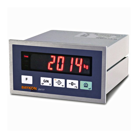
3.1 Display The weight display of BX11 is seven segments LED. At the right side of the display there are two LED’s for indicating the net and the unit ( standard kg ), also the left side of the display for indicating the gross, center of zero and unstable. -
Page 12: Key Pad
PC via serial port. 3.3 Key Lock BX11 has ability to lock the keys to avoid unauthorized person’s interfere. The key(s) which would be locked are programmed at parameter [ 115 ] (Page 41 ). - Page 13 BX11 & BX11 MB Panel type rear view BX11 PB Panel type rear view BX11 PN Panel type rear view BX11 EN Panel type rear view BX11 CO Panel type rear view Page 11 of 92 BX11 Smart Process Indicator, Technical Manual, Rev. 1.2, May 2013...
-
Page 14: Accessories
The following accessories are supplied with the instrument or can be purchased separately. 3.5.1 Accessories supplied with the instrument The following accessories are supplied together with the BX11 instruments. If any part is missed, please contact to your supplier. 3-pos and 3,81 mm pitch green plug for... -
Page 15: Installation
EMC interference in the cabinet. If possible protect BX11 instruments with the faraday cage or install them in separate section or install them far a way from this kind of equipments. Connect parallel reverse diodes to the DC inductive loads like relays, solenoids etc. -
Page 16: Power Supply Connection And Grounding
There is a DIP switch on BX11’s rear side and its position should be “ON” ( downward ) to change the metrological related parameters including calibration. There is no need to open the housing to change the position of this DIP switch. If there is not set-up DIP switch on the instrument for industrial usage, its position is always ON. -
Page 17: Load Cell Connection
Figure 4.3. In 4-wire installations the sense and excitation pins with the same polarity should be short circuited at the connector side. If you have junction box, use 6 wire cable between BX11 and the junction box, and short circuit these pins at junction box for better performance. 4 wire LC connection 6 wire LC connection Figure 4.3 - Load cell connections... -
Page 18: Rs 485 And Modbus-Rtu Connection
BX11AN is programmable to 4 – 20 mA, 0 – 20 mA, 0 – 5 V or 0 – 10 V analogue output types. Analogue connections are done as indicated below in Figure 4.6 and Figure 4.7. Figure 4.6 - BX11 AN Voltage output connections Page 16 of 92 BX11 Smart Process Indicator, Technical Manual, Rev. 1.2, May 2013... -
Page 19: Profibus Connection (Only Bx11 Pb )
Ground 4.3.7 Profinet Connection (only BX11 PN ) Profinet connection is done as indicated below in Figure 4.9. Figure 4.9 - BX11 PN serial interface connections Page 17 of 92 BX11 Smart Process Indicator, Technical Manual, Rev. 1.2, May 2013... -
Page 20: Ethernet Connection (Only Bx11 En )
Figure 4.10 - HUB connection The PC connection cabling will be done via cross cable as shown below. IP address blocks and gateway address of BX11 and PC should be the same in cross connection. Figure 4.11 - Cross PC connection Warning: Connect the shield to the reference ground or shield pin of the power connector. -
Page 21: Canopen Connection (Only Bx11 Co )
Figure 4.12 - HUB connection The PC connection cabling will be done via cross cable as shown below. IP address blocks and gateway address of BX11 and PC should be the same in cross connection. Figure 4.13 - Cross PC connection Warning: Connect the shield to the reference ground or shield pin of the power connector. -
Page 22: Digital Inputs And Outputs Connection
4.3.10 Digital Inputs and Outputs Connection Digital Inputs: BX11 inputs which are independently programmable for zeroing, taring, clear, print, key lock, peak, hold, and as a fieldbus input port. If the input is programmed as a fieldbus input port, the input status is transferred to the PLC by fieldbus command. - Page 23 Figure 4.16 - BX11 Inputs connection diagram Digital Outputs: BX11 instruments digital outputs are can be used as a standard, threshold and window. Threshold and window outputs are also programmable positive or negative polarity. Digital outputs of BX11 are also programmable as a fieldbus port to control them with a fieldbus commands.
-
Page 24: Commissioning
BX11 before field bus interfacing. Install IndFace1X to your PC. IndFace1X software is used for easy programming, calibration and testing of BX11 instruments. After checking the performance of instruments with IndFace1X, you can begin to use BX11 in your application. Page 22 of 92... -
Page 25: Serial Data Outputs
UTPUTS BX11 indicator family has different kind of serial interfaces like RS 232, RS 485 and Ethernet etc. In this section, you will find the data structure of different type of the data outputs via these serial ports except field bus interfaces. -
Page 26: Fast Continuous Data Output
The format of the data output in Print mode can be selected in 3 different type forms in the parameter group [ 04- ] . Only continuous format is available more than one interface. Page 24 of 92 BX11 Smart Process Indicator, Technical Manual, Rev. 1.2, May 2013... -
Page 27: Bsi Data Structure
Multi Line-2 Format 5.4 BSI Data Structure All new generation BAYKON instruments launched on the market support the standardized command set BSI data form, depending on the functionality of the instrument. This easy data format gives the reliable and speedy interface advantages with communicating PLC or PC for process control or transactional applications. - Page 28 Syntax error ( not recognized the received command ) Overload − Underload Note: CHK, CR and LF will not be shown in below data format descriptions in this section. Page 26 of 92 BX11 Smart Process Indicator, Technical Manual, Rev. 1.2, May 2013...
- Page 29 [ADR][G][STATUS][VOLTAGE VALUE] Example Command : 01G Response : 01GA234 (Power supply is 23.4 VDC) 01GA150 (Power supply is 15.0 VDC) 01GA090 (Power supply is 9.0 VDC) Page 27 of 92 BX11 Smart Process Indicator, Technical Manual, Rev. 1.2, May 2013...
- Page 30 SP Type is 1 byte ASCII char. Use ‘L’ for SPx_L and use ‘H’ for SPx_H. SP VALUE data is 8-byte ASCII char with dot and non-significant zeros on the left. Page 28 of 92 BX11 Smart Process Indicator, Technical Manual, Rev. 1.2, May 2013...
- Page 31 Status must be stable in 2 seconds time out delay. If so, Ack is send. If it can not be stable in time out delay, Nack is send. Page 29 of 92 BX11 Smart Process Indicator, Technical Manual, Rev. 1.2, May 2013...
- Page 32 Data length change according to number of digital outputs. Outputs are implemented to ASCII char of 4-bit. ‘1111’ is implemented to char ‘F’. OUTPUTS Bit wise ASCII Page 30 of 92 BX11 Smart Process Indicator, Technical Manual, Rev. 1.2, May 2013...
- Page 33 Status must be stable in 2 seconds time out delay. If so, Ack is send. If it can not be stable in time out delay, Nack is send. Page 31 of 92 BX11 Smart Process Indicator, Technical Manual, Rev. 1.2, May 2013...
- Page 34 Checksum = 0 − (0x30 + 0x31 + 0x50 + 0x53 + 0x2B + 0x30 + 0x30 + 0x30 + 0x31+ 0x32 + 0x33 + 0x2E + 0x34) = 0 − 0x02B7 = 0x49 = Char ‘4’ and Char ‘9’ Page 32 of 92 BX11 Smart Process Indicator, Technical Manual, Rev. 1.2, May 2013...
-
Page 35: Programming And Calibration
ROGRAMMING AND ALIBRATION In this section you will find the programming and calibration procedure of BX11 indicator according to your application. The signs those take place on the lower right corner of the keys indicate the function of the keys in programming menu. -
Page 36: Fast Access To The Calibration
Especially for legal metrological usage, please don’t forget to turn the power off and “OFF” position the calibration DIP switch to start operation. Page 34 of 92 BX11 Smart Process Indicator, Technical Manual, Rev. 1.2, May 2013... - Page 37 80 _ M.LOGIC REC. RECORDS CAL. COUNT. 9_ _ 90 _ CTRL PRMT TESTS KEY PAD RS232C RS485 INPUTS OUTPUTS 99 _ PRMT. PRT ALL PRMT. DEFAULT Page 35 of 92 BX11 Smart Process Indicator, Technical Manual, Rev. 1.2, May 2013...
-
Page 38: Programming
6.4 Programming [0--] Interface Block You can reach the parameters about serial interface of BX11 indicator in this section. The data output modes can be used once except continuous data output. [00-] RS 232C Serial Port This sub-block includes the parameters about the 1 serial interface of BX11. - Page 39 ( Page 53 ) 6 : Fast continuous mode ( Page 24 ) ( * ) Warning : Use for Baykon remote displays interfacing. CR and LF should be enabled. [011 3] Baud Rate 0 : 1200 Baud 2400 Baud...
- Page 40 1 : Modbus RTU Answer is delayed 20 msec after Request is received. This property is very helpful for slow PLC systems [03-] Ethernet (Only BX11 EN) This sub-block includes the parameters related with the Ethernet of BX11 indicator. [030 4 ] Data Format 0 : No data transfer.
- Page 41 [045 XY] Line Feed After Printing X=0,1 : 0 means the forward feeding and 1 means the backward feeding. Y=0,1,2….9 : Enter the number of the feed lines after data printing Page 39 of 92 BX11 Smart Process Indicator, Technical Manual, Rev. 1.2, May 2013...
- Page 42 1 : 32 bit float, decimal point implied [051 000] Rack Address The Profibus rack address of BX11 will be entered via keypad between 001 to 126. [06-] Profinet (Only BX11 PN) This sub-block includes the parameters related with the Profinet interfaces of BX11 indicator.
- Page 43 [1--] Configuration Block In this block the parameters take place which are being used to set BX11 according to your application. [11-] Start Up [112 1] Tare Memory 0 : No. 1 : Tare value is stored at power off.
- Page 44 6 : Hold during active 7 : Peak during active 8 : Field bus input [132 0] Input 2 ( only BX11, BX11 AN, BX11 MB and BX11 EN ) 0 : Not used 1 : Zero 2 : Tare...
- Page 45 If the scale is stabile during this time, the scale is accepted as a stabile to process zeroing, tare, print etc. commands. It can be entered up to 9.9 sec. Page 43 of 92 BX11 Smart Process Indicator, Technical Manual, Rev. 1.2, May 2013...
- Page 46 After calibration this parameter will be zeroed. If value of this parameter is zero, that means no gravity adjustment had been performed after calibration. Page 44 of 92 BX11 Smart Process Indicator, Technical Manual, Rev. 1.2, May 2013...
- Page 47 Calibration involves emptying the scale then placing a known test weight on an empty platform and allowing the BX11 indicator to capture values for zero and span. Calibration is performed as; 1. Press < Enter > at the [ 301 ] prompt to start the calibration.
- Page 48 If the value of the test weights that will be used is different from the value shown on the display, type the new value via tare and zero keys. A minimum of 20% of scale capacity is necessary for calibration; BAYKON recommends 50 to 100%. A calibration error will result if insufficient weight is used.
- Page 49 Warning: The scale capacity and increment shall be entered before performing eCal. This parameter lets you to perform calibration without using any test weights. BX11 A/D coefficients are adjusted in production for increasing eCal accuracy. The calibration coefficients are calculated by scale capacity, total load cell capacity, load cell full scale output, and estimated dead load.
- Page 50 < Tare > key to decrease the analogue signal level by taking the full capacity value as reference without placing any weight. Page 48 of 92 BX11 Smart Process Indicator, Technical Manual, Rev. 1.2, May 2013...
- Page 51 0 : No function on output 2 1 : Threshold (Active High) 2 : Threshold (Active Low) 3 : Window (Active High) 4 : Window (Active Low) 5 : Fieldbus output Page 49 of 92 BX11 Smart Process Indicator, Technical Manual, Rev. 1.2, May 2013...
- Page 52 4 : Window (Active Low) 5 : Fieldbus output [703 0] Output 4 ( only BX11, BX11 AN, BX11 MB and BX11 EN ) Refer to Table 6.1 to select the output function. 0 : No function on output 4...
- Page 53 Press < Enter > key. [ Ld dEf ] message appears on the display. Press < Tare > key for loading default parameter values or press < F > key to go [ 9- ] sub block. The scale build parameters and calibration is not changed. Page 51 of 92 BX11 Smart Process Indicator, Technical Manual, Rev. 1.2, May 2013...
-
Page 54: Analogue ( Only Bx11 An )
ONLY BX11 AN is programmable to 4 – 20 mA, 0 – 20 mA, 0 – 5 V or 0 – 10 V analogue output types. Analog output is automatically adjusted to the weighing range after the calibration. The mid value of the analog output is set to zero load at bipolar usage. -
Page 55: Modbus Rtu ( Only Bx11 Mb )
ODBUS ONLY BX11 MB indicator has a Modbus RTU interface over RS 485 / RS 232C serial port. This interface can be programmable to High-Low or Low-High for different type of PLC’s. You can find below the difference of these data formats and some companies using these formats. Two types are available as;... - Page 56 Scale unstable - Wait until scale become stable - Check grounding wiring The Calibration DIP switch is not ON position. - Check the calibration DIP switch. Page 54 of 92 BX11 Smart Process Indicator, Technical Manual, Rev. 1.2, May 2013...
- Page 57 Increment Write this command after writing values to 40031-32 addresses. (2) Only set point low addresses are used if the set point is programmed as standard. Page 55 of 92 BX11 Smart Process Indicator, Technical Manual, Rev. 1.2, May 2013...
- Page 58 Exception codes: 1: Function code is not supported. 2: Out of beginning and ending address range. 3: Invalid value entrance or wrong byte number. 4: Operation error. Page 56 of 92 BX11 Smart Process Indicator, Technical Manual, Rev. 1.2, May 2013...
- Page 59 01,03,00,C8,00,01,05,F4 Answer of digital outputs 01,03,02,00,04,B9,87 (Output-3 is Active) Read Setpoint-1 Low 01,03,00,C9,00,02,14,35 Answer of Setpoint-1 Low 01,03,04,00,00,03,E8,FA,8D Load Set point 1 Low = 5000 01,10,00,C9,00,02,04,00,00,13,88,32,C3 Page 57 of 92 BX11 Smart Process Indicator, Technical Manual, Rev. 1.2, May 2013...
- Page 60 A simple example of program: PLC application files are available in CD which is supplied together with the instrument. Page 58 of 92 BX11 Smart Process Indicator, Technical Manual, Rev. 1.2, May 2013...
-
Page 61: Profibus ( Only Bx11 Pb )
45.45 kbps, 93.75 kbps, 187.5 kbps, 500 kbps, 1.5 Mbps, 3 Mbps, 6 Mbps and 12 Mbps. No ‘baud rate’ instance exists. After programming Profibus related parameters of the BX11 PB indicator, you can communicate with the instrument. GSD file is available in CD which is supplied together with the instrument. -
Page 62: Gsd Configuration
Profibus data is consist of 2 x Input 2 words and 2 x Output 2 words. GSD configuration for PLC programmers is shown in Figure 9.1. Figure 9.1 - GSD Configuration Page 60 of 92 BX11 Smart Process Indicator, Technical Manual, Rev. 1.2, May 2013... -
Page 63: Profibus Dp Data Structure
Indicated weight 00001 Gross weight Read Command 00010 Tare weight D5 … D1 Response 00011 Calibration Status (Refer to Table 9.1 ) 00100 Not used 01110 Page 61 of 92 BX11 Smart Process Indicator, Technical Manual, Rev. 1.2, May 2013... - Page 64 - Calibration loading is not enough Errors - Check test weight loading (Write test weight value to 1 0010 0011 Dword of PLC Output to BX11 PB Input then restart the calibration) - Check load cell connections Calibration load value entry Error 0010 0100 - Test weight is too small.
- Page 65 Set Point-2 Low 10010 Set Point-2 High 10011 Set Point-3 Low 10100 Set Point-3 High 11111 Use the Expanded Command list ( Refer to Table 9.2 ) Page 63 of 92 BX11 Smart Process Indicator, Technical Manual, Rev. 1.2, May 2013...
- Page 66 XXX.XXX 01001010 Increment Table 9.2 - Expanded Command List (1) Write this command after writing values to 1 Dword then apply this command with New CMD Page 64 of 92 BX11 Smart Process Indicator, Technical Manual, Rev. 1.2, May 2013...
- Page 67 Programming steps of frequent used …… Reading a weight value: 1. Check the D12…D15 bits of ‘BX11 PB Output to PLC Input 2 Dword’. 2. If there is not any error, read a weight value ( gross, net or tare), Zero Calibration procedure: 1.
-
Page 68: Profinet ( Only Bx11 Pn )
LED State Description Comment No Link No link, no communication present Ethernet link established, no Green Link communication present Ethernet link established, Green, flickering Activity communication present Page 66 of 92 BX11 Smart Process Indicator, Technical Manual, Rev. 1.2, May 2013... -
Page 69: Profinet Parameters
Secondary DNS If DHCP is disabled, obtain secondary DNS manually. Default is ‘208.67.220.220’. Host Name Enter a unique host name to the instrument. Default is ‘ ’. Page 67 of 92 BX11 Smart Process Indicator, Technical Manual, Rev. 1.2, May 2013... -
Page 70: Gsdml Configuration
10.2 GSDML Configuration Profinet data structures of BX11 PN includes 2 x Input 2 words and 2 x Output 2 words. GSDML configuration for PLC programmers is shown in Figure 10.1. Figure 10.1 - GSDML Configuration Page 68 of 92... -
Page 71: Profinet Data Structure
Indicated weight 00001 Gross weight Read Command 00010 Tare weight D5 … D1 Response 00011 Calibration Status (Refer to Table 10.1 ) 00100 Not used 01110 Page 69 of 92 BX11 Smart Process Indicator, Technical Manual, Rev. 1.2, May 2013... - Page 72 - Calibration loading is not enough Errors - Check test weight loading (Write test weight value to 1 0010 0011 Dword of PLC Output to BX11 PN Input then restart the calibration) - Check load cell connections Calibration load value entry Error 0010 0100 - Test weight is too small.
- Page 73 Set Point-2 Low 10010 Set Point-2 High 10011 Set Point-3 Low 10100 Set Point-3 High 11111 Use the Expanded Command list ( Refer to Table 10.2) Page 71 of 92 BX11 Smart Process Indicator, Technical Manual, Rev. 1.2, May 2013...
- Page 74 XXX.XXX 01001010 Increment Table 10.2 - Expanded Command List (1) Write this command after writing values to 1 Dword then apply this command with New CMD. Page 72 of 92 BX11 Smart Process Indicator, Technical Manual, Rev. 1.2, May 2013...
- Page 75 Programming steps of frequent used …… Reading a weight value: 1. Check the D12…D15 bits of ‘BX11 PN Output to PLC Input 2 Dword’. 2. If there is not any error, read a weight value ( gross, net or tare), Zero Calibration procedure: 1.
-
Page 76: Ethernet Tcp/Ip ( Only Bx11 En )
THERNET ONLY Ethernet output of BX11 EN is programmable to BSI command set, Continuous data output, Fast continuous data output, Modbus TCP/IP High-Low, Modbus TCP/IP Low-High. The first three data structures can be find in the related sections indicated in the table below. - Page 77 : IP address of the PC or Device to be connected automatically. Remote IP Remote Port : Ethernet connection point of PC or Device to be connected automatically. Page 75 of 92 BX11 Smart Process Indicator, Technical Manual, Rev. 1.2, May 2013...
-
Page 78: Modbus Tcp Data Structure
Low/High voltage det. 40004 Tare weight 40006 Gross weight 40008 Status Motion, Net mode, Data ok, (image of register 40003) Description None Zero 40009 Control Tare Clear Print Page 76 of 92 BX11 Smart Process Indicator, Technical Manual, Rev. 1.2, May 2013... - Page 79 Power Supply For example: 23.4 VDC is indicated as integer 234 value. Input-1 40200 Status of Inputs Input-2 Output-1 Output-2 40201 Status of Outputs Output-3 Output-4 Page 77 of 92 BX11 Smart Process Indicator, Technical Manual, Rev. 1.2, May 2013...
- Page 80 2. Load the decimal '188' to 40030 to start Zero calibration. 3. Check the low byte of 40033. it is decimal '3' during zero calibration process. Page 78 of 92 BX11 Smart Process Indicator, Technical Manual, Rev. 1.2, May 2013...
- Page 81 (Instrument is ready for calibration) Zero Calibration 01,10,00,1D,00,01,02,00,BC Span Calibration Command with Span 01,10,00,1D,00,03,06,00,DC,00,00,C3,50 value 50000 Total LC capacity Command with Total 01,10,00,1D,00,03,06,00,EC,00,01,86,A0 LC capacity value 100000 Page 79 of 92 BX11 Smart Process Indicator, Technical Manual, Rev. 1.2, May 2013...
- Page 82 01,03,00,C8,00,01 Answer of digital outputs 01,03,02,00,04 (Output-3 is Active) Read Setpoint-1 Low 01,03,00,C9,00,02 Answer of Setpoint-1 Low 01,03,04,00,00,03,E8 Load Set point 1 Low = 5000 01,10,00,C9,00,02,04,00,00,13,88 Page 80 of 92 BX11 Smart Process Indicator, Technical Manual, Rev. 1.2, May 2013...
-
Page 83: Canopen ( Only Bx11 Co )
LSS services in progress A guard- (NMT-Slave or NMT- Red, double flash Error count event master) or heartbeat event (Heartbeat consumer) has occurred. Bus off (Fatal Event) Bus off. Page 81 of 92 BX11 Smart Process Indicator, Technical Manual, Rev. 1.2, May 2013... -
Page 84: Eds Configuration
12.1 EDS Configuration CANopen data structures of BX11 CO includes 1 x TxPDO ( 64 bit ) and 1 x RxPDO ( 64 bit ). EDS configuration for PLC programmers is shown in Figure 12.1. Figure 12.1 - EDS Configuration Page 82 of 92 BX11 Smart Process Indicator, Technical Manual, Rev. -
Page 85: Canopen Data Structure
– Motion Detection Dynamic 00000 Indicated weight 00001 Gross weight Read Command D37 … D33 Response 00010 Tare weight 00011 Calibration Status (Refer to Table 12.1) Page 83 of 92 BX11 Smart Process Indicator, Technical Manual, Rev. 1.2, May 2013... - Page 86 - Calibration loading is not enough Errors - Check test weight loading (Write test weight value to 0010 0011 RxPDO 1 (R_DW1) of PLC Output to BX11 CO Input then restart the calibration) - Check load cell connections Calibration load value entry Error 0010 0100 - Test weight is too small.
- Page 87 Set Point-2 High ( 1 ) 10011 Set Point-3 Low ( 1 ) 10100 Set Point-3 High 11111 Use the Expanded Command list ( Refer to Table 12.2) Page 85 of 92 BX11 Smart Process Indicator, Technical Manual, Rev. 1.2, May 2013...
- Page 88 Decimal point XXXXX.X XXXX.XX XXX.XXX 01001010 Increment Table 12.2 - Expanded Command List (1) Write this command with writing values to D0~D33 bits then apply New CMD. Page 86 of 92 BX11 Smart Process Indicator, Technical Manual, Rev. 1.2, May 2013...
- Page 89 4. The low byte of Calibration Status changes to decimal '1' at the end of the Span calibration. 5. If the low byte of Calibration Status is '9', check the high byte of Calibration Status to understand the calibration error. Page 87 of 92 BX11 Smart Process Indicator, Technical Manual, Rev. 1.2, May 2013...
-
Page 90: Trouble Shooting
ROUBLE HOOTING BX11 weighing indicator had been designed as a very reliable and virtually error free instrument. However if there is an error occurs, do not attempt to repair the equipment before understanding what caused the error. Note the problems you have with your instrument and the error messages shown on the display. Then try to solve the problem according to the error table given below. -
Page 91: Parametre's Default Table
Parallel inputs test Parallel outputs test Filter Filter mV indication Parallel I / 0 Printing Parameters Outputs Whole parameters Input 1 Load default parameters Input 2 Page 89 of 92 BX11 Smart Process Indicator, Technical Manual, Rev. 1.2, May 2013... -
Page 92: Calibration Table
= Max Capacity / e recommended values are given in the table below. You can use this table to select your Max and e values. Max value can be entered freely. Page 90 of 92 BX11 Smart Process Indicator, Technical Manual, Rev. 1.2, May 2013... -
Page 93: Frequently Asked Questions
: Short circuit your com port RXD and TXD pins. Check if the sending data is received or not by using any terminal software. You may test also BX11 com ports as described in The Diagnostic Tests section on Page 50 by short circuiting RXD and TXD terminals. - Page 94 NOTES : Page 92 of 92 BX11 Smart Process Indicator, Technical Manual, Rev. 1.2, May 2013...
- Page 96 Kimya Sanayicileri Organize Sanayi Bölgesi Organik Cad. No:31 Tepeören, 34956 Istanbul, TURKEY Tel : +90 216 593 26 30 (pbx) Fax : +90 216 593 26 38 e-mail: baykonservis@baykon.com http:// www.baykon.com...
Need help?
Do you have a question about the BX11 and is the answer not in the manual?
Questions and answers