Table of Contents
Advertisement
Advertisement
Table of Contents

Related Manuals for Zline 30"

Summary of Contents for Zline 30"
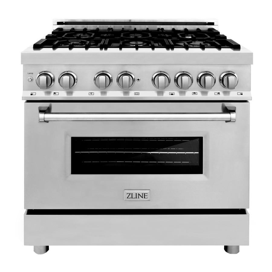
- Page 1 Range Installation Guide and Users Manual...
- Page 2 Our distributors and ou r service partners are ready to answer any questions you may have regarding installation of your ZLINE product. This manual will help you learn to use the product in the safest, most efficient manner, and care for it so that it may give you the highest satisfaction for years to come.
- Page 3 WARNING! Important Safety Information Read this instruction booklet before installing Please read and follow these important and using the appliance. instructions for the safety of your home and of the people living in it. The manufacturer will not be responsible for any damage to property or to persons caused by incorrect WARNING! installation or improper use of the appliance.
-
Page 4: Table Of Contents
Table of Contents Warranty and Service Befor Ins tallation Installin t g Anti-Tip Stability Device Installation Requirements Installation Adjacent to Kitchen Cabinets Exhaust Hood Installation Electrica Co nnection Applianc Ser ving Ga Co nnection Ga Co nversion Ga Bu rners Installatio C n hecklist Fina Pre... -
Page 5: Warranty And Service
Warranty and Service All products carry a two year part s warranty. Service on all products shall be carried out by factory-trained professionals only. For warranty service please contact customer service. Replacement Parts Only authorized replacement parts may be used in performing service on this appliance. - Page 6 Product Specifications Dimensions...
-
Page 7: Befor Ins E Tallation
Before Installation This appliance shall only be installed by an autho- A manual valve shall be installed in an accessible lo- rized professional. cation in the gas line external to the appliance for the purpose of turning on and shutting off the gas The appliance shall be installed in accordance with to the appliance. -
Page 8: Installin T G He Le Gs
Installing the Legs The ranges must be used with the legs properly installed. Four height-adjustable legs are shipped with the range, in a foam container above the range. Before installing the legs, position the appliance near its final location as the legs are not suitable for moving the appliance over long distances. -
Page 9: Anti-Tip Stability Device
WARNING! A child or adult can tip the range and be killed; Re-engage the anti-tip device if the range is moved. Failure to do so can result in death or serious burns to children or adults. Installing the Anti-Tip Stability Device The Anti-tip bracket shipped with the range must be properly secured to the rear wall as shown in the picture below. -
Page 10: Installation Requirements
Electrical Installation Requirements A properly grounded and horizontally-mounted For the best look, the worktop should be level with the electrical receptacle Type NEMA 14-50R should cabinet countertop. This can be accomplished by rais- be installed no higher than 3˝ (7.6cm) above the ing the unit using the adjustment spindles on the legs. -
Page 12: Electrical Connection
Electrical Connection The appliance shall be connected to a single phase Failure to follow these instructions electric line rated at 120/208Vac or 120/240Vac and could result in serious injury or death. 60Hz frequency. CAUTION! Electric Power Rating: • 120/240Vac: 12A Max Label all wires prior to disconnecting when servicing controls. -
Page 13: Applianc Ser E Ving
Wiring/Schematic Diagram Places on Backside of Panel and on Installation Booklet... -
Page 14: Ga Co S Nnection
Gas Connection All gas connections must comply with national and Manual Shut-off Valve local codes. The gas supply line (service) must be the same size or greater than the inlet line of the appli- This valve is not shipped with the appliance and ance. -
Page 15: Gas Conversion
Manifold pressure should be checked with a manom- Pressure Test Point Stopper Valve eter and comply with the values indicated below. To avoid gas leaks, the pressure test-point stopper • Natural Gas->430”W.c.P valve and gasket supplied with the range must be •... -
Page 16: Ga Co S Nversion
Gas Conversion Procedure The gas conversion procedure for this range cap, reverse its direction and screw it again firm- ly against the cap. The white plastic attachment includes: has arrows indicating the position for natural gas 1. Pressure Regulator (NAT) and LP gas (LP). 2. -
Page 17: Ga Bu S Rners
Surface Burners 1. Light one burner at a time and set it to the MINIMUM position (small flame). 2. Remove the knob. 3. The range is equipped with a safety valve. Using a small-size slotted screwdriver, locate the choke screw to the right or left until the burner flame is adjusted to desired minimum. 4. -
Page 18: Fina Pre L Paration
Final Preparation All stainless steel body parts should be wiped with hot, soapy water and with a stainless steel cleanser. If build-up occurs, do not use steel wool, abrasive cloths, cleaners, or powders! If it is necessary to scrape stainless steel to remove encrusted materials, soak with hot, wet cloths to loosen the material, and then use a wood or nylon scraper. -
Page 19: Use Ma R Nual
Important User Information! Reposition all worktop burners/oven/broiler oven door gasket. The door gasket is essential for a burners’ controls in OFF position good seal. Care should be taken not to rub, dam- after use of the appliance. age, or move the gasket. Do not use oven cleaning products. -
Page 20: Roo Ve M Ntilation
Important User Information! WARNING! Surface Cooking Important! Any child or adult can tip the range, verify the anti-tip device has been properly Be sure to set all worktop/oven/broiler burners installed and engaged. controls to the OFF position after use of the appliance. - Page 21 Important User Information! Important! Surface Burner Operation / Electric Ignition To activate the electric ignition, simply turn the con- Reset all, worktop/oven/broiler burner, controls trol knob counter-clockwise to maximum power in the OFF position after use of the appliance. (*position*), then press the knob in to start the flow 1.
-
Page 22: Ove Co N Oking
Important User Information! Tips For Using Pans Correctly Placement of Oven Racks Attention! Always place oven racks in desired location while oven is cool. If rack must be moved while oven is hot, do Always ensure that bottom and handles of pans not let potholder contact hot heating element in oven. - Page 23 Important User Information! -rials come into contact with the heating elements or interior surfaces of the oven until they have had suf-ficient time to cool. Other surfaces of the appliance may become hot enough to cause burns, for example, oven vent openings and surfaces near these openings, oven doors, and oven glass window.
-
Page 24: Usin T G He Ven O
Important User Information! -
Page 25: Maintaining Your Range
Maintaining Your Range Replacing the Oven Bulbs ►Cleaning Stainless Steel WARNING! For the best results use a stainless steel cleaner prod- uct with a soft sponge or cloth with a warm soap and water solution. Never use abrasive powders or liquids. Disconnect power before servicing unit. -
Page 26: Troubleshooting
Trouble Shooting Guide Oven Problem Possible Cause and / or Remedy Range Does Not Function Range is not connected to electrical power. ASK A PROFESSIONAL to check power circuit breaker, wiring and fuses. Self-Clean Cycle Does Not Activate Door is not shut tight enough for automatic door lock to latch. Broil Does Not Work Temperature control knob is rotated too far past broil position (500°F);... - Page 27 Trouble Shooting Guide Oven Problem Possible Cause and/or Remedy Pre-Heating Indicator Lights Up This is a FAULT alarm indication the failure of the cooling fan(s). Try Intermittently With Sound Alarm ON resetting by turning both selectors to the OFF position. If the error is not repaired, CALL A QUALIFIED TECHNICIAN FOR DIAGNOSIS AND REPAIR.
-
Page 28: Location Of Appliance Tags
Location of Appliance Tags The rating tag shows the model and serial number of your range. The tag is located under the front edge of the range cooktop. The tag is visible when the oven door is open. (See Illustration) A=Rating tag(s) located on the back plate of the oven B=Wiring schematic diagram places behind the backside panel and on the installation booklet. - Page 29 ZLINE Kitchen and Bath Two Locations: 916 Delaware Avenue Marysville, Ohio 43040 350 Parr Circle Reno, NV 89512 www.zlinekitchen.com 1-866-528-0571...
Need help?
Do you have a question about the 30" and is the answer not in the manual?
Questions and answers